Sign In
Upload
Manuals
Brands
Automation Direct Manuals
Control Panel
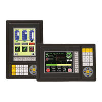
C-more EA1-T6CL
User Manuals: Automation Direct C-more EA1-T6CL Screen
Manuals and User Guides for Automation Direct C-more EA1-T6CL Screen. We have
1
Automation Direct C-more EA1-T6CL Screen manual available for free PDF download: Hardware User Manual
Automation Direct C-more EA1-T6CL Hardware User Manual (181 pages)
Graphic Color Panels
Brand:
Automation Direct
| Category:
Control Panel
| Size: 21 MB
Table of Contents
Table of Contents
6
Chapter 1: Getting Started
12
Introduction
12
Conventions Used
13
Product Overview - EA1-T4CL
14
Product Overview - EA1-T6CL
15
Agency Approvals
15
Part Number Key
16
Product Label Examples
16
Serial Number and Date Code Format
16
Quick Start Steps
17
Step 1 - Unpack and Inspect
17
Step 2 - Install Optional Hardware Accessories
18
Step 3 - Become Familiar with Available Communication Ports
19
Step 4 - Install C-More Color Micro-Graphic Panel
20
Enclosure Clearances
22
Step 5 - Install the Programming Software and Develop a Project
23
Step 6 - Connect C-More Color Micro-Graphic Panel to Computer
24
Step 7 - Providing Power to the C-More Color Micro-Graphic Panel
25
Step 8 - Accessing the C-More Color Micro-Graphic Panel Setup Screens
26
Step 9 - Choose C-More Color Micro-Graphic Panel to PLC Protocol & Cables
27
Step 10 - Connect C-More Color Micro-Graphic Panel to PLC
28
Chapter 2: Specifications
30
Available Models
30
EA1-T4CL Specifications
31
EA1-T6CL Specifications
33
EA1-T4CL Panel Dimensions
35
EA1-T6CL Panel Dimensions
36
Communications Port
37
Chemical Compatibility
38
Chapter 3: Accessories
49
Accessories
49
C-More Micro-Graphic Programming Software
50
20-Button Landscape (Horizontal) Keypad Bezel for 6-Inch Panels
53
21-Button Portrait (Vertical) Keypad Bezel for 6-Inch Panels
56
D-SUB 15-Pin 90-Degree Communication Port Adapter
59
D-SUB 15-Pin to Terminal Block Adapter
59
Clear Screen Overlay
60
Chapter 4: Installation and Wiring
62
Safety Guidelines
62
Introduction
63
Panel Cutout Dimensions
64
Wiring Guidelines
65
Chapter 5: System Setup Screens
67
Introduction
67
Accessing the System Setup Screens
68
System Setup Screens Flowchart
69
Setup Menu
70
Information Menu
71
Setting Menu
72
Brightness
72
Touch/Key Beep
72
Clear User Memory
72
Reset to Factory Default
72
Calibration
73
Calibration
74
Reset to Factory Default
75
Hourglass
76
Rotation
77
Test Menu
78
PLC Enquiry Test
78
Buzzer Test
78
Touch Panel Test
78
Display Test
79
Exit
82
Chapter 6: PLC Communications
84
Introduction
84
Introduction
85
C-More Micro-Graphic Communication Ports
86
Directlogic Plcs Password Protection
87
Compatibility and Connection Charts
87
Automationdirect Controllers
88
RS-422A/RS-485A Communications
88
Allen-Bradley
88
GE, Mitsubishi, Omron, Modicon and Siemens
88
How to Use the Compatibility and Connection Charts
89
Cables from Automationdirect
96
Cables from Automationdirect - Wiring Diagrams
98
User Constructed Cables - Wiring Diagrams
106
RS-422A Multi-Drop Wiring Diagram Example
118
RS-485A Multi-Drop Wiring Diagram Example
120
Chapter 7: Maintenance
123
Project Backup
123
Check Operating Environment
123
Check Operating Voltage
123
Check Transmit and Receive Indicators
124
Check Physical Conditions
124
Run Tests under the System Setup Screens
125
Check Settings under the System Setup Screens
126
Cleaning the Display Screen
126
Check Project Functionality
127
Checks from the C-More Micro-Graphic Programming Software
127
Chapter 8: Troubleshooting
130
C-More Micro-Graphic Panel Does Not Power up
130
Display Is Blank
130
Display Is DIM
131
No User Program
131
Lost Firmware - Red 'Update Mode' Screen Displayed
132
Updating Firmware
132
No Communications between Panel and PC (Personal Computer)
133
No Communications between Panel and PLC
135
Panel & PLC Error Codes
136
C-More Micro-Graphic Panel Runtime Errors
137
Reset to Factory Default
138
Electrical Noise Problems
138
Chapter 9: Replacement Parts
140
Replacement Parts Overview
140
Replacement Parts
140
Customizing the Function Keys Insert Label
141
Appendix A: PLC Protocol Error Codes
143
Introduction
143
C-More Micro-Graphic Panel Error Code Table
144
Modbus Protocols Error Code P499 Explanation
145
Automationdirect CLICK
145
Automationdirect Directlogic - Modbus (Koyo
145
Modicon Modbus RTU
145
Entivity Modbus RTU
145
Productivity3000 Error Code P499
146
Directlogic Error Code P499 Explanation
147
Directlogic - K-Sequence PLC Error Code Table
147
Directlogic - Directnet PLC Error Codes
147
Allen-Bradley Error Code P499 Explanation
148
Allen-Bradley DF1 Protocol - PLC Error Code Tables
149
Allen-Bradley DH485 Protocol - PLC Error Code Tables
151
GE Error Code P499 Explanation
153
GE SNPX Protocol - PLC Error Code Tables
154
GE SNPX Protocol - PLC Error Code Tables
159
Mitsubishi FX Protocol - PLC Error Codes
163
Mitsubishi Q / Qna Series - PLC Error Codes
163
Mitsubishi Q / Qna Series - PLC Error Codes
164
Omron Error Code P499 Explanation
165
Omron Host Link Protocol - PLC Error Code Table
166
Omron FINS Protocol - PLC Error Code Table
167
Omron FINS Protocol - PLC Error Code Table
168
Siemens Error Code P499 Explanation
170
Siemens PPI Protocol - PLC Error Code Table
171
Appendix B: C-More Micro-Graphic Panel Runtime Errors
173
Introduction
173
Runtime Errors
174
Serial Port2 - Loop Back Test
179
Advertisement
Advertisement
Related Products
Automation Direct C-more EA1-T4CL
Automation Direct Categories
Controller
Measuring Instruments
I/O Systems
Control Unit
DC Drives
More Automation Direct Manuals
Login
Sign In
OR
Sign in with Facebook
Sign in with Google
Upload manual
Upload from disk
Upload from URL