Sign In
Upload
Manuals
Brands
AUMA Manuals
Controller
SA 48.1 SAR 25.1
AUMA SA 48.1 SAR 25.1 Manuals
Manuals and User Guides for AUMA SA 48.1 SAR 25.1. We have
1
AUMA SA 48.1 SAR 25.1 manual available for free PDF download: Operation Instructions Manual
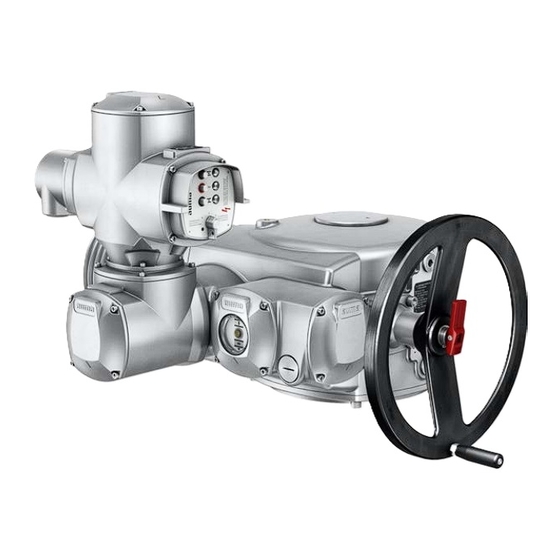
AUMA SA 48.1 SAR 25.1 Operation Instructions Manual (92 pages)
Multi-turn actuators
Brand:
AUMA
| Category:
Controller
| Size: 2 MB
Table of Contents
Table of Contents
2
Safety Instructions
5
Basic Information on Safety
5
Range of Application
5
Warnings and Notes
6
References and Symbols
6
Identification
8
Name Plate
8
Short Description
11
Transport, Storage and Packaging
12
Transport
12
Storage
13
Packaging
13
Assembly
14
Mounting Position
14
Handwheel Fitting
14
Multi-Turn Actuator: Mount to Valve/Gearbox
15
Output Drive Type a
15
4.3.1.1. Stem Nut: Finish Machining
16
4.3.1.2. Multi-Turn Actuator (with Output Drive Type A): Mount to Valve
17
Output Drive Types B and E
18
4.3.2.1. Multi-Turn Actuator with Output Drive Types B: Mount to Valve/Gearbox
18
Accessories for Assembly
19
Stem Protection Tube for Rising Valve Stem
19
Electrical Connection
21
Basic Information
21
Connection with Control Box
23
Electrical Connection of Actuator Controls
24
Electrical Connection S/SH (AUMA Plug/Socket Connector)
24
5.3.1.1. Terminal Compartment : Open
25
5.3.1.2. Cable Connection
26
5.3.1.3. Terminal Compartment : Close
27
Electrical Connection of Actuator
28
Motor Connection
29
5.4.1.1. Motor Connection Compartment: Open
29
5.4.1.2. Motor Cables: Connect
29
5.4.1.3. Motor Connection Compartment: Close
30
S/SH Electrical Connection (AUMA Plug/Socket Connector)
31
5.4.2.1. Terminal Compartment: Open
31
5.4.2.2. Cable Connection
32
5.4.2.3. Terminal Compartment: Close
33
Accessories for Electrical Connection
34
Actuator Controls on Wall Bracket
34
Parking Frame
35
DS Intermediate Frame for Double Sealing
36
External Earth Connection
36
Operation
37
Manual Operation
37
Engage Manual Operation
37
Manual Operation: Disengage
38
Motor Operation
38
Local Operation
38
Actuator Operation from Remote
39
Indications
40
Indication Lights
40
Optional Indications
40
Mechanical Position Indication Via Indicator Mark
40
Signals (Output Signals)
42
Feedback Signals Via Output Contacts (Binary)
42
Feedback Signals (Analogue)
42
Commissioning (Basic Settings)
43
Heat-Up Time for Low Temperature Version
43
Switch Compartment: Open
43
Torque Switching: Set
44
Limit Switching: Set
44
End Position CLOSED (Black Section): Set
45
End Position OPEN (White Section): Set
45
Test Run
46
Direction of Rotation at Mechanical Position Indicator: Check
46
Direction of Rotation at Hollow Shaft/Stem: Check
46
Limit Switching: Check
47
Switch Compartment: Close
47
Commissioning (Optional Equipment Settings)
49
Potentiometer
49
Potentiometer: Set
49
RWG Electronic Position Transmitter
49
Measuring Range: Set
50
EWG 01.1 Electronic Position Transmitter
50
Measuring Range: Set
51
Current Values : Adjust
52
LED End Position Signalling: Switch On/Off
53
Intermediate Positions: Set
53
Running Direction CLOSE (Black Section): Set
54
Running Direction OPEN (White Section): Set
54
Mechanical Position Indicator: Set
54
Commissioning Controls Settings
56
Actuator Controls: Open
56
Type of Seating: Set
56
Push-To-Run Operation or Self-Retaining: Set
57
Running Indication (Blinker Transmitter): Activate/Deactivate
58
Torque Fault in Collective Fault Signal: Activate/Deactivate
58
Leds for Torque Fault, Phase Failure, Motor Protection
58
Positioner
59
Input Ranges (Signal Type) for Setpoint and Actual Value
59
Behaviour on Loss of Signal (Actuator Reaction)
60
Adjustment in End Positions
61
Sensitivity Setting
63
EMERGENCY Command (EMERGENCY - OPEN/EMERGENCY - CLOSE)
64
Actuator Controls: Close
64
PTC Tripping Device (Option): Test
65
Corrective Action
66
Faults During Commissioning
66
Fuses
66
Fuses Within the Actuator Controls
66
Fuses Within the Control Box
68
Motor Protection (Thermal Monitoring)
69
Servicing and Maintenance
70
Preventive Measures for Servicing and Safe Operation
70
Maintenance
71
Disposal and Recycling
71
Technical Data
72
Technical Data Multi-Turn Actuators
72
Technical Data Actuator Controls
74
Technical Data Control Box
77
Spare Parts
79
Multi-Turn Actuators SA
79
Sa 48.1/Sar 25.1
79
Actuator Controls am 01.1/AM
81
Wall Bracket
83
Control Cabinet for Switchgear
85
Certificates
87
EU Declaration of Incorporation / Declaration of Conformity
87
Index
88
Addresses
90
Advertisement
Advertisement
Related Products
AUMA SA 48.1
AUMA SA 48.1 SAR 07.1
AUMA SA 40.1
AUMA SAEx 07.2
AUMA SAR 100
AUMA SAExC Series
AUMA SAExC 16.1
AUMA SARN 14.1
AUMA SAE 14.6 Series
AUMA SAEx 30.1
AUMA Categories
Controller
Industrial Equipment
Control Unit
Control Systems
Outboard Motor
More AUMA Manuals
Login
Sign In
OR
Sign in with Facebook
Sign in with Google
Upload manual
Upload from disk
Upload from URL