Sign In
Upload
Manuals
Brands
AudioCodes Manuals
Network Router
Mediant 800A
AudioCodes Mediant 800A Network Router Manuals
Manuals and User Guides for AudioCodes Mediant 800A Network Router. We have
2
AudioCodes Mediant 800A Network Router manuals available for free PDF download: Hardware Installation Manual
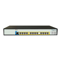
AudioCodes Mediant 800A Hardware Installation Manual (56 pages)
Media Gateway & Enterprise SBC (E-SBC)
Brand:
AudioCodes
| Category:
Gateway
| Size: 2 MB
Table of Contents
Table of Contents
3
1 Introduction
11
2 Unpacking the Device
13
3 Physical Description
15
Physical Dimensions and Operating Environment
15
Table 3-1: Physical Dimensions and Operating Environment
15
Front Panel Description
16
Ports and Buttons
16
Figure 3-1: Mediant 800B Front Panel
16
Figure 3-2: Mediant 800C Front Panel
16
Table 3-2: Front Panel Description
16
Leds Description
18
LAN Interface Leds
18
FXS Leds
18
Table 3-3: LAN Leds Description
18
Table 3-4: FXS Leds Description
18
FXO Leds
19
BRI Leds
19
Table 3-5: FXO Leds Description
19
Table 3-6: BRI Leds Description
19
E1/T1 (PRI) Leds
20
Status Led
20
Table 3-7: E1/T1 Leds Description
20
Table 3-8: STATUS LED Description
20
Power Leds
21
Table 3-9: POWER LED Description
21
Table 3-10: AC PWR LED Description
21
Table 3-11: DC PWR LED Description
21
Rear Panel Description
22
Figure 3-3: Mediant 800B Rear Panel
22
Figure 3-4: Mediant 800C Rear Panel
22
Table 3-12: Rear Panel Description
22
4 Mounting the Device
25
Desktop Mounting
25
Figure 4-1: Rubber Foot Attached to Underside of Device
25
Wall Mounting
26
Figure 4-2: Attaching the Mounting Brackets to Chassis
26
Figure 4-3: Attaching the Chassis with Mounting Brackets to Wall
27
19-Inch Rack Mounting
28
Using a Pre-Installed Rack Shelf
28
Using Mounting Brackets
29
Figure 4-4: Mounting Brackets
29
Figure 4-5: Attaching the Mounting Brackets
29
5 Cabling the Device
31
Grounding and Surge Protection
31
Figure 5-1: Grounding the Device
32
Connecting to LAN
33
Figure 5-2: LAN Port-Pair Groups and Web Interface String Names
33
Table 5-1: RJ-45 Connector Pinouts for Gbe/Fe
33
Figure 5-3: Connecting the LAN Ports
34
Connecting to Analog Devices
35
Connecting the FXS Interfaces
35
Figure 5-4: RJ-11 Connector Pinouts for FXS Interface
35
Connecting the FXO Interfaces
36
Figure 5-5: Connecting FXS Interfaces
36
Figure 5-6: RJ-11 Connector Pinouts for FXO Interface
37
Figure 5-7: Connecting FXO Interfaces
37
Connecting the FXS Analog Lifeline
38
Figure 5-8: RJ-11 Connector Pinouts for FXS Lifeline
38
Figure 5-9: Cabling FXS Lifeline
38
ISDN BRI Interfaces
39
Connecting to BRI Lines
39
Figure 5-10: RJ-45 Connector Pinouts for BRI Ports
39
Connecting PSTN Fallback for BRI Lines
40
Figure 5-11: Cabling BRI Ports
40
Figure 5-12: RJ-45 Connector Pinouts for BRI PSTN Fallback
40
Figure 5-13: Cabling (Ports 1 and 2) PSTN Fallback
41
Connecting ISDN E1/T1 Interfaces
42
Connecting to ISDN PRI (E1/T1) Trunks
42
Figure 5-14: RJ-48C Connector Pinouts for E1/T1
42
Figure 5-15: Cabling E1/T1 Ports
42
Connecting PSTN Fallback for E1/T1 Trunks
43
Figure 5-16: RJ-48C Connector Pinouts for E1/T1 PSTN Fallback
43
Figure 5-17: Cabling PRI Ports for PSTN Fallback
44
Connecting to a Computer for Serial Communication
45
Figure 5-18: Cabling Serial Interface
45
Connecting the OSN Server
46
Table 5-2: OSN Server Platforms
46
Figure 5-19: Cabling OSN Server Ports
47
Connecting to Power
48
Connecting to AC Power
48
Table 5-3: AC Power Specifications
48
Connecting to DC Power
49
Figure 5-20: Connecting to the Power Supply
49
Table 5-4: DC Power Specifications
49
Figure 5-21: Connecting DC Power Plug to DC Inlet
50
Figure 5-22: Plugging AC Power Cord into AC/DC Adaptor
51
6 Maintenance - Replacing the Power Fuse
53
Figure 6-1: Opening the Fuse Cavity
53
Table 6-1: Allowed Fuses for the Device
53
Figure 6-2: Removed Power Fuse
54
Advertisement
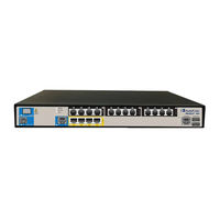
AudioCodes Mediant 800A Hardware Installation Manual (42 pages)
Gateway and E-SBC SIP Protocol
Brand:
AudioCodes
| Category:
Network Router
| Size: 1 MB
Table of Contents
Table of Contents
3
Abbreviations and Terminology
7
Customer Support
7
Weee Eu Directive
7
Documentation Feedback
8
Related Documentation
8
1 Introduction
9
2 Unpacking the Device
11
3 Physical Description
13
Physical Dimensions and Operating Environment
13
Table 3-1: Physical Dimensions and Operating Environment
13
Front Panel Description
14
Ports and Buttons
14
Figure 3-1: Mediant 800B Front Panel
14
Figure 3-2: Mediant 800 Front Panel
14
Table 3-2: Front Panel Description
14
Leds Description
16
LAN Interface Leds
16
FXS Leds
16
Table 3-3: LAN Leds Description
16
Table 3-4: FXS Leds Description
16
FXO Leds
17
BRI Leds
17
Table 3-5: FXO Leds Description
17
Table 3-6: BRI Leds Description
17
E1/T1 Leds
18
Operational Status Leds
18
Power Leds
18
Table 3-7: E1/T1 Leds Description
18
Table 3-8: STATUS Leds Description
18
Table 3-9: POWER Leds Description
18
Rear Panel Description
19
Figure 3-3: Rear Panel
19
Table 3-10: Rear Panel Description
19
4 Mounting the Device
21
Desktop Mounting
21
Figure 4-1: Rubber Foot Attached to Underside of Device
21
19-Inch Rack Mounting
22
Using a Pre-Installed Rack Shelf
22
Using Mounting Brackets
23
Figure 4-2: Mounting Bracket (Right)
23
Figure 4-3: Attaching the Mounting Brackets
23
5 Cabling the Device
25
Grounding the Device
25
Figure 5-1: Grounding the Device
25
Connecting to LAN
26
Figure 5-2: LAN Port-Pair Groups and Web Interface String Names
26
Table 5-1: RJ-45 Connector Pinouts for Gbe/Fe
26
Figure 5-3: Connecting the LAN Ports
27
Analog Devices
28
Connecting the FXS Interfaces
28
Figure 5-4: RJ-11 Connector Pinouts for FXS Interface
28
Figure 5-5: Connecting FXS Interfaces
28
Connecting the FXO Interfaces
29
Figure 5-6: RJ-11 Connector Pinouts for FXO Interface
29
Figure 5-7: Connecting FXO Interfaces
29
Connecting the FXS Analog Lifeline
30
Figure 5-8: RJ-11 Connector Pinouts for FXS Lifeline
30
Figure 5-9: Cabling FXS Lifeline
30
ISDN BRI Interfaces
31
Connecting to BRI Lines
31
Figure 5-10: RJ-45 Connector Pinouts for BRI Ports
31
Figure 5-11: Cabling BRI Ports
31
Connecting the PSTN Fallback for BRI Lines
32
Figure 5-12: Cabling (Ports 1 and 2) PSTN Fallback
32
Connecting to ISDN PRI (E1/T1) Trunks
33
Figure 5-13: RJ-48C Connector Pinouts for E1/T1
33
Figure 5-14: Cabling E1/T1 Ports
33
Connecting to a Computer for Serial Communication
34
Figure 5-15: Orderable RS-232 Cable Adapter
34
Figure 5-16: Cabling Serial Interface (RJ-45) on Mediant 800B
35
Connecting the OSN Server
36
Table 5-2: OSN Server Platforms
36
Figure 5-17: Cabling OSN Server Ports
37
Powering up the Device
38
Figure 5-18: Connecting to the Power Supply
38
Table 5-3: Power Specifications
38
6 Maintenance - Replacing the Power Fuse
39
Figure 6-1: Opening the Fuse Cavity
39
Figure 6-2: Removed Power Fuse
39
Table 6-1: Allowed Fuses for the Device
39
A Installing Centos Ver. 4.7 on OSN Server
41
Advertisement
Related Products
AudioCodes Mediant 800 MSBR
AudioCodes Mediant 800Ci uCPE
AudioCodes Mediant 500L MSBR
AudioCodes Mediant 500 MSBR
AudioCodes Mediant
AudioCodes Mediant MSBR Series
AudioCodes Mediant 500Li MSBR
AudioCodes Mediant 800
AudioCodes Mediant 800B
AudioCodes Mediant 800 MSBG
AudioCodes Categories
Gateway
IP Phone
Controller
Network Router
Conference System
More AudioCodes Manuals
Login
Sign In
OR
Sign in with Facebook
Sign in with Google
Upload manual
Upload from disk
Upload from URL