Sign In
Upload
Manuals
Brands
Atlas Copco Manuals
Finishers
DYNAPAC Svedala Demag DF 135 C
Atlas Copco DYNAPAC Svedala Demag DF 135 C Manuals
Manuals and User Guides for Atlas Copco DYNAPAC Svedala Demag DF 135 C. We have
1
Atlas Copco DYNAPAC Svedala Demag DF 135 C manual available for free PDF download: Operation & Maintenance Manual
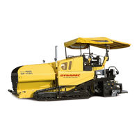
Atlas Copco DYNAPAC Svedala Demag DF 135 C Operation & Maintenance Manual (236 pages)
Paver finisher, Type 35
Brand:
Atlas Copco
| Category:
Finishers
| Size: 6 MB
Table of Contents
Table of Contents
3
Preface
11
General Safety Instructions
12
Acts, Directives, Accident Prevention Regulations
12
Warning Instructions
12
Prohibitive Signs
14
Protective Gear
15
Environmental Protection
16
Fire Prevention
16
Further Instructions
17
A Correct Use and Application
19
B Vehicle Description
21
Application
21
Description of Assemblies and Functions
22
Vehicle
23
Construction
23
Danger Zones
26
Safety Devices
27
Emergency Stop Button
27
Steering
27
Horn
27
Ignition Key / Lights
27
Main Switch (17)
28
Hopper Transport Safeguards (18)
28
Screed Transport Safeguard (19)
28
Latch for Protective Roof (20)
28
Technical Data, Standard Configuration
30
Dimensions (All Dimensions in MM)
30
Allowed Angle of Rise and Slope
31
Allowed Angle of Driving up
31
Weights DF 115 C (All Weights in T)
32
Weights DF 135 C (All Weights in T)
32
Performance Data DF 115 C
33
Performance Data DF 135 C
34
Traction Drive/Chassis
35
Engine DF 115 C
35
Engine DF 135 C
35
Hydraulic System
35
Material Compartment (Hopper)
36
Material Conveying
36
Material Distribution
36
Screed Lifting Device
37
Electrical System
37
Location of Instruction Labels and Identification Plates
38
Identification Label for the Paver Finisher (6)
40
Standards
41
Continuous Sound Level DF115C, Deutz TCD 2013L46
41
Operating Conditions During Measurement
41
Measuring Point Configuration
41
Continuous Sound Level DF135C, Deutz TCD 2013L06
42
Operating Conditions During Measurement
42
Measuring Point Configuration
42
Vibration Acting on the Entire Body
43
Vibrations Acting on Hands and Arms
43
Electromagnetic Compatibility (EMC)
43
C1.1 Transportation
45
Safety Regulations for Transportation
45
Transportation on Low-Bed Trailers
46
Preparations
46
Driving Onto the Low-Bed Trailer
48
Secure the Paver Finisher in Its Position to the Low-Bed Trailer
49
After Transportation
49
Transportation
50
Preparations
50
Traction Drive
52
Loading by Crane
53
Towing
54
Safely Parking the Vehicle
57
D1.4 Operation
59
Safety Regulations
59
Operating Elements
60
Operating Panel
60
Remote Control
78
Front Side
79
Reverse Side
80
D3.1 Operation
81
Operating Elements on the Paver Finisher
81
Batteries (71)
81
Battery Main Switch (72)
81
Transport Safeguards for the Hopper (73)
82
Mechanical Screed Transport Safeguard (to the Left and the Right Beneath the Driver's Seat) (74)
83
Seat Lock (Behind the Driver's Seat) (75)
83
Separator Fluid Spraying System (80) (O)
84
On / off Switch for Additional Headlight in the Roof (85)
85
On / off Switch for Fuel Tank Filler Pump (85A)
85
On / off Switch Special Lighting (85B)
85
On/Off Switch
85
Exhaust of Asphalt Vapours (85C)
85
On/Off Switch of Work Headlights (85D)
86
On/Off Switch of Flasher (85E)
86
On / off Switch Connection Sockets (85F)
86
Locking of the Collapsible Roof (LH and RH on the Roofs Console) (86)
86
Hydraulic Folding Roof (87) (O)
87
Electric Setting of the Transportation Volume of the Conveyor (O) (88)
88
Conveyor Limit Switches (89)
89
Ultrasonic Auger Limit Switches (90) (Left and Right)
90
Sockets for Working Lights (Left and Right) (92)
90
Pressure Control Valve for Screed Charging/Relieving (93)
91
Pressure Control Valve for Screed Stop with Pretensioning (93A)
91
Pressure Gauge for Screed Charging/Relieving and Screed Stop with Pretensioning (93B)
91
Central Lubrication Unit (O) (100)
92
Track Cleaner (O) (101)
92
Particle Filter - Control Light (102) (O)
93
Front and Side Window (O) (103)
94
Adjustment of Screed Eccentric (O) (104)
95
D4.6 Operation
97
Preparation of Operation
97
Required Devices and Aids
97
Before Starting Work (in the Morning or When Starting Paving)
98
Checklist for the Machine Operator
98
Starting the Paver Finisher
100
Before Starting the Paver Finisher
100
Normal" Starting
100
External Starting (Starting Aid)
101
After Starting
102
Indicator Lamps
102
Battery Charge Indicator (1)
102
Oil Pressure Indicator Lamp for the Traction Drive (2)
102
Preparations for Paving
104
Separating Agent
104
Screed Heater
104
Direction Marks
104
Loading/Distributing Material
105
Starting for Paving
107
Checks During Paving
109
Paver Function
109
Quality of the Layer
109
Paving with Functions „Screed Control, Stopping of Paver Finisher" and „Screed Loading / Unloading
110
General
110
Screed Charging/Relieving
111
Screed Control with the Paver Finisher Standing Still (Floating Position with and Without Prestressing)
111
Screed Control with the Paver Finisher at Standstill - with Floating Position Prestressing
112
Adjusting the Pressure
112
Adjustment of Pressure for the Loading/Offloading of the Screed
113
Screed Control Pressure with the Paver Finisher at Standstill - Set the Floating Position with Prestressing (O)
113
Interrupting/Terminating Operation
114
During Breaks (E.g. the Material Supply Truck Is Late)
114
During Extended Interruptions (E.g. Lunch Break)
114
When Work Is Finished
115
Malfunctions
117
Querying the Error Messages of the Traction Engine
117
Display of the Number Code
117
Error Messages
120
FMI-Codes
125
Problems During Paving
126
Malfunctions on the Paver Finisher or Screed
128
Emergency Device/Steering, Drive System
131
E01 Set-Up and Modification
135
Special Notes on Safety
135
Auger
136
Height Adjustment
136
Auger Crossbeam Installed in a Fixed Position
136
Mechanical Adjustment with Ratchet (Optional)
137
In Case of Hydraulic Adjustment (Option)
137
Auger Extension, Auger Type I
139
Mounting Extension Parts
140
Mounting Support Tube Extensions
141
Installing Tunnel Plates
142
Installing Additional Braces
143
Auger Mounting Chart for Ø 310 MM Auger
144
Auger Mounting Chart for Ø 380 MM Auger
145
Auger Extension, Auger Type II
146
Mounting Extension Parts
147
Auger Modification Plan
149
Screed
151
Electrical Connections
151
Remote Controls
151
Grade Control
151
Auger Limit Switches
151
Working Lights
151
F1.0 Maintenance
153
Notes Regarding Safety
153
F2.3 Maintenance Overview
155
Maintenance Review
155
F3.0 Maintenance - Conveyor
157
Maintenance - Conveyor
157
Maintenance Intervals
158
Points of Maintenance
158
Chain Tightness of the Conveyor (1)
159
The Drive of Conveyor (to the Left/To the Right) (2)
160
F4.1 Maintenance - Auger
161
Maintenance - Auger Sub-Unit
161
Maintenance Intervals
162
Points of Maintenance
162
Auger - Outer Bearing (1)
162
Auger Planetary Gear (2)
163
Drive Chain (3) of the Transport Augers
164
Auger Case (4)
166
F5.1 Maintenance - Engine
169
Maintenance - Engine Sub-Unit
169
Maintenance Intervals
170
Points of Maintenance
170
Engine Fuel Tank (1)
172
Engine Lube-Oil System (2)
173
Engine Fuel System (3)
175
Engine Air Filter (4)
177
Coolant System of the Engine (5)
178
Engine Drive Belt (6)
178
Engine Exhaust System (7)
179
F6.0 Maintenance - Hydraulic System
181
Maintenance - Hydraulic System
181
Maintenance Intervals
182
Points of Maintenance
182
Hydraulic Oil Tank (1)
182
Suction/Return Flow Hydraulic Filter (2)
184
Venting the Filter
185
High Pressure Filter (3)
186
Pump Distribution Gear (4)
187
Hydraulic Hoses (5)
188
F7.2 Maintenance - Running Gear
189
Maintenance - Running Gear
189
Maintenance Intervals
190
Points of Maintenance
190
Track Tightness (1)
191
Planetary Gear (2)
192
F8.1 Maintenance - Electronic System
193
Maintenance - Electronic System
193
Maintenance Intervals
194
Points of Maintenance
194
Batteries (1)
197
Generator (2)
198
Adjustment of Belt Tightness
200
Replacement of Belt
201
Checking / Adjusting Belt Tension
202
If Necessary, Adjust the Belt Tension
202
Electric Fuses (3)
203
Type of Machine: Conventional Electronics
203
Switch Box
203
Fuses in the Switching Cabinet (B)
204
Relays in the Switching Cabinet (C)
205
Fuses on the Operating Panel
206
Relays on the Operating Panel
207
Type of Machine: PLC- Electronics
208
Switch Box
208
Fuses in the Switching Cabinet
209
Relays in the Switching Cabinet (C)
211
Fuses on the Operating Panel
212
F9.0 Maintenance - Points of Lubrication
213
Maintenance- Points of Lubrication
213
Maintenance Intervals
214
Points of Maintenance
214
Central Lubrication (1)
215
Bearings (2)
219
F10.0 Checks, Decommissioning
221
Tests, Check-Up, Cleaning, Stopping
221
Maintenance Intervals
222
General Observation
223
Checks by a Specialist
223
Cleaning
224
Conservation of Paver Finisher
225
Downtime up to 6 Months
225
Downtime between 6 Months and 1 Year
225
Re-Commissioning
225
F11.0 Lubricants and Fuels
227
Lubricants and Fuels
227
Hydraulic Oil
228
Instructions Referring to the Oil Types Applied
229
Filling Volumes
230
Instructions to Change from Mineral Oil to Synthetic Oil / from Synthetic Oil to Mineral Oil
234
Caterpillar Drive - Planetary Gear
234
Advertisement
Advertisement
Related Products
Atlas Copco DYNAPAC Svedala Demag DF 115 C
Atlas Copco DC 600
Atlas Copco D2163-Q
Atlas Copco DWS VSD+
Atlas Copco DD 44
Atlas Copco DD 60
Atlas Copco DSS
Atlas Copco D1703M-BG
Atlas Copco D500
Atlas Copco PAS 8 DDM-W 305
Atlas Copco Categories
Power Tool
Air Compressor
Drill
Tools
Grinder
More Atlas Copco Manuals
Login
Sign In
OR
Sign in with Facebook
Sign in with Google
Upload manual
Upload from disk
Upload from URL