Sign In
Upload
Manuals
Brands
Astronics Manuals
Portable Generator
Racal Instruments 3100R
Astronics Racal Instruments 3100R Manuals
Manuals and User Guides for Astronics Racal Instruments 3100R. We have
1
Astronics Racal Instruments 3100R manual available for free PDF download: User Manual
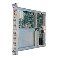
Astronics Racal Instruments 3100R User Manual (420 pages)
VXIbus Arbitrary Waveform Generator
Brand:
Astronics
| Category:
Portable Generator
| Size: 9 MB
Table of Contents
Table of Contents
8
Chapter 1
28
Introduction
28
What's in this Manual
28
What's in this Chapter
29
Conventions Used in this Manual
29
Introduction
29
3152B Feature Highlights
30
Figure 1-1, Racal Instruments 3152B
30
3100M/3100R Feature Highlights
31
3201A/3202A Feature Highlights
31
Arbconnection Feature Highlights
31
Figure 1-2, Arbconnection Control Panels
32
Figure 1-3, Arbconnection Wave Composer Example
32
General Description
33
Output Waveforms
33
Figure 1-4, Arbconnection Pulse Composer Example
33
Figure 1-5, Arbconnection Serial Data Composer Example
33
Run Modes
34
Frequency Control and Accuracy
35
Phase-Lock Loop (PLL)
35
Signal Integrity
35
Frequency Agility
35
Amplitude
35
Remote Control
36
Carrier Configuration (Different Model Numbers)
36
Specifications
37
Safety Considerations
38
Figure 1-6, Configurations: 3151B, 3152B, 3100R-3152B, and 3100M-3152B
38
Options
39
Supplied Accessories
39
Front Panel Connectors
39
Output (Out)
40
Sync out (Sync)
40
Trig/Pll in (Trg/Pll)
40
EXT SCLK (EXT 10Mhz)
41
EXT 10Mhz
41
Output Waveforms
41
Standard (FIXED) Waveforms
41
Arbitrary (User) Waveforms
42
Sequenced Waveforms
42
Figure 1-7, Segment 1 - Sine (X)/X Waveform
43
Figure 1-8, Segment 2 - Sine Waveform
43
Figure 1-9, Segment 3 - Pulse Waveform
43
Modulated Waveforms
44
Sweep
44
Figure 1-10, Sequenced Waveforms
44
Frequency Hopping
45
Astronics Test Systems I
45
Amplitude Hopping
45
Fsk
45
Psk
45
Ask
45
Digital Pulse Waveforms
46
Half Cycle Waveforms
46
Counter/Timer
46
General Run Modes
46
Continuous Mode
47
Triggered Mode
47
Gated Mode
47
Burst Mode
47
Trigger Sources
47
Modulation Run Modes
48
Synchronization of Multiple 3152B Modules
48
PLL Synchronization
49
Phase Modulation
49
Filters
49
Output State
49
Programming the 3152B
50
Chapter 2
52
Installation
52
Preparation for Use
52
Logical Address Selection
52
Figure 2-1, Switch S1 (Set to Logical Address 2)
52
Local Bus Configuration
53
Figure 2-2, Local Bus (LBUS) Jumper Locations
54
Installation
55
Controlling the Instrument from a Remote Device
55
Installing Software Utilities
55
Connecting to a LAN Network
56
LAN Configuration
56
Choosing a Static IP Address
57
Connecting to the USB Port
58
Chapter 3
60
Operation
60
Overview
60
Legacy to Modern Mode
60
Output Termination
61
Input/Output Protection
62
Power On/Reset Defaults
62
Turning the Output on
62
Turning the SYNC Output on
62
Selecting the SYNC Source
63
Changing the SYNC Position and Width
64
Example: Generating a Simple Waveform
64
Amplitude-Offset Interaction
65
Selecting an Output Function
66
Selecting a Run Mode
66
Continuous Run Mode
67
Triggered Run Mode
67
Re-Triggered Run Mode
67
Gated Run Mode
68
Burst Run Mode
69
Selecting the Trigger Source
70
Selecting the Trigger Level
71
Selecting the Trigger Slope
71
Using Trigger Delay
72
Activating the Backplane Ttltrg Lines
72
Example: Generating Standard Waveforms
73
Using the Apply Command
73
Generating Standard Waveforms
74
Standard Waveform Parameters
76
Using the Apply Command
76
Generating Arbitrary Waveforms
77
What Are Arbitrary Waveforms
78
Managing Arbitrary Waveform Memory
78
Memory Management Commands
79
Figure 3-1, Arbconnection Example of a Complex Waveform
79
Loading Arbitrary Waveforms
81
Selecting 12-Bit or 16-Bit Waveform Resolution
82
Selecting Code Compatibility with the Legacy 3152A
82
Changing the Sample Clock Frequency
83
Using the External Sample Clock Input
84
Generating Sequenced Waveforms
85
Sequence Commands
86
Figure 3-2, Sequence Table Created in Arbconnection
86
Controlling the Sequence Advance Modes
88
Generating Modulated Waveforms
89
Modulation Parameters
90
Controlling the Carrier Frequency
91
Controlling the Carrier Base Line
91
Using the Digital Pulse Generator
91
Pulse Design Limitations
93
Generating Half Cycle Waveforms
93
Using the Counter/Timer
94
Counter/Timer Limitations
95
Synchronizing through the Local Bus
96
Using the 3201A/3202A Signal Amplifier
97
Connecting the 3202A/3202A Signal Amplifier
98
Controlling the 3201A/3202A Output
98
Chapter 4
100
Arbconnection
100
What's in this Chapter
100
What Is Arbconnection
100
System Requirements
100
Installing Arbconnection
100
Startup & Communication Options
101
Arbconnection Features
101
Figure 4-1, Startup & Communication Options Dialog Box
101
Main Window
102
Control Panels
102
Figure 4-2, Arbconnection Menu and Link Bar
102
Figure 4-3, Main Panels Toolbar
102
The Operation Panels
104
Figure 4-4, Operation Panel Selection
104
Output
105
Figure 4-5, Output Panel
105
Run Mode
106
Figure 4-6, Run Mode Control Panel
107
Standard
108
Figure 4-7, Standard Waveforms Panel
109
Arbitrary/Sequence
110
Figure 4-8, Arbitrary/Sequence Panel
111
Using the Memory Partition Table
112
Figure 4-9, Memory Partition Table
113
Using Waveform Studio
114
Figure 4-10, Waveform Studio
115
Figure 4-11, Sequence Table Example
116
Half Cycle
118
Figure 4-12, Half Cycle Panel
118
The Modulation Panels
119
Figure 4-13, Modulation Panels
119
Figure 4-14, FM Panel
120
Sweep
122
Figure 4-15, am Panel
122
Figure 4-16, Sweep Modulation Panel
123
Fsk/Psk/Ask
124
Figure 4-17, FSK/PSK/ASK Modulation Panel
125
Ampl/Freq Hop
126
Figure 4-18, Amp/Freq Hop Panel
127
Auxiliary Panels
128
Figure 4-19, Access to Auxiliary Panels
128
Counter/Timer
129
Figure 4-20, Counter/Timer Panel
129
Pulse Generator
130
Figure 4-21, Digital Pulse Generator Panel
130
X-Instrument Sync
131
Figure 4-22, X-Instrument Synchronization Pool List
132
Figure 4-23, Adjacent Synchronization between Two Instruments
133
Figure 4-24, LBUS Synchronization between Adjacent Slots
134
Figure 4-25, ECLT Synchronization Example
134
The System Panels
135
General/Filters
135
Figure 4-26, System Panels
135
Figure 4-27, General/Filters Panel
136
Calibration
137
The Composers Panels
137
Figure 4-28, Calibration Panel
137
The Wave Composer
138
The Wave Composer Menu Bar
138
Figure 4-29, Composers Panel
138
File Menu
139
Figure 4-30, Wave Composer Screen
139
Edit Menu
140
Figure 4-31, Open Waveform Dialog Box
140
View Commands
141
Astronics Test Systems
141
Wave Menu
142
Figure 4-32, Zooming in on Waveform Segments
142
The Toolbar
144
The Waveform Screen
144
Figure 4-33, Generating Distorted Sine Waves from the Built-In Library
144
Figure 4-34, Toolbar Icons
144
Figure 4-35, Waveform Screen
145
Generating Waveforms Using Equation Editor
146
Figure 4-36, Equation Editor Dialog Box
146
Writing Equations
148
Equation Conventions
148
Typing Equations
149
Equation Examples
150
Figure 4-37, Equation Editor Example
150
Figure 4-38, Using the Equation Editor to Modulate Sine Waveforms
151
Figure 4-39, Using Equation Editor to Add Second Harmonic Distortion
152
Figure 4-40, Using the Equation Editor to Generate Exponentially Decaying Sinewave
153
Combining Waveforms
154
Figure 4-41, Using Equation Editor to Build Amplitude Modulated Signal with Sidebands
154
Figure 4-42, Combining Waveforms into Equations
155
The Pulse Composer
156
The Pulse Composer Menu Bar
156
File Menu
156
Figure 4-43, Pulse Composer Screen
157
Edit Menu
158
View Menu
158
Figure 4-44, Pulse Editor
159
Figure 4-45, Pulse Editor Options
159
Tools Menu
160
The Pulse Composer Toolbar
160
Creating Pulses
160
Figure 4-46, Pulse Composer Toolbar
160
Figure 4-47, Complete Pulse Train Design
161
Figure 4-48, Section 5 of the Pulse Train Design
161
Setting the Pulse Editor Options
162
Figure 4-49, Selecting Pulse Editor Options
162
Using the Pulse Editor
163
Figure 4-50, Using the Pulse Editor
164
Pulse Example, Section 1
166
Figure 4-51, Building Section 1 of the Pulse Example
166
Pulse Example, Section 2
167
Figure 4-52, Building Section 2 of the Pulse Example
167
Pulse Example, Section 3
168
Figure 4-53, Building Section 3 of the Pulse Example
168
Pulse Example, Section 4
169
Pulse Example, Section 5
169
Figure 4-54, Building Section 4 of the Pulse Example
169
Downloading the Pulse Train
170
Figure 4-55, Building Section 5 of the Pulse Example
170
Interpreting the Download Summary
171
Figure 4-56, Pulse Editor Download Summary
171
The FM Composer
172
The Menu Bar
172
Figure 4-57, FM Composer Opening Screen
172
File Menu
173
Wave Commands
173
Figure 4-58, Generating Sine Modulation Using the FM Composer
174
The 3D Composer
175
Shared Horizontal Controls
176
Figure 4-59, 3D Composer Screen
176
Figure 4-60, Parameters Tab
177
Figure 4-61, Expanded Parameters Options Dialog Box
177
Vertical Controls
178
Graphical Screens
179
Figure 4-62, 3D Vertical Controls
179
Designing 3D Profiles
180
Figure 4-63, 3D Waveform Graphs
180
Figure 4-64, 3D Chirp Design Example
181
The Command Editor
182
Logging SCPI Commands
182
Figure 4-65, Command Editor
182
Figure 4-66, Log File Example
183
Chapter 5
184
Programming Reference
184
What's in this Chapter
184
Introduction to SCPI
184
Command Format
185
Command Separator
185
The MIN and MAX Parameters
185
Querying Parameter Setting
186
Query Response Format
186
SCPI Command Terminator
186
SCPI Parameter Type
186
Numeric Parameters
186
Discrete Parameters
187
Boolean Parameters
187
Arbitrary Block Parameters
187
Binary Block Parameters
187
SCPI Syntax and Styles
187
Alternative Command Set (HS Commands)
188
Invoking HS Command Mode
188
Rules for Using HS Command Mode
189
Legacy Vs. Modern Command Set
190
3152B Legacy Commands
191
Table 5-1, 3152B SCPI Command Summary for 3152A Emulation
191
Table 5-2, 3152B SCPI Command Summary
193
3100R/M-3152B Commands
196
Instrument & Output Control Commands
206
Table 5-3, Instrument & Output Control Commands Summary
206
Run Mode Commands
220
Table 5-4, Run Mode Commands
221
Standard Waveform Control Commands
227
Table 5-5, Standard Waveform Control Commands Summary
227
Arbitrary Waveform Control Commands
233
Table 5-6, Arbitrary Waveform Command Summary
234
Figure 5-1, Definite Length Arbitrary Block Data Format
236
Figure 5-2, 3152B 16-Bit Waveform Data Point Representation
237
Figure 5-3, 3152A 12-Bit Waveform Data Point Representation
237
Figure 5-4, Segment Address and Size Example
240
The Apply Control Commands
241
Using the Apply Commands
241
Table 5-7, Apply Control Commands
242
Sequenced Waveform Control Commands
248
Table 5-8, Sequence Control Commands
249
Figure 5-5, 64-Bit Sequence Table Download Format
250
Modulated Waveform Global Control Commands
254
Table 5-9, Modulated Waveform Global Commands
254
Modulation Control Commands
256
Table 5-10, Modulated Waveform Control Commands
256
AM Programming
258
FM Modulation Programming
259
Sweep Programming
262
ASK Modulation Programming
267
PSK Modulation Programming
269
Frequency Hopping Modulation Programming
271
Modulation Programming
271
Digital Pulse Programming
276
Table 5-11, Digital Pulse Commands Summary
277
Table 5-12, Half Cycle Commands Summary
281
Counter Control Commands
283
Table 5-13, Counter Commands Summary
283
Synchronization Commands
285
Table 5-14, Synchronization Command Summary
287
LXI System Configuration Commands
290
System Commands
293
Astronics Test Systems
293
Table 5-15, System Commands Summary
293
Table 5-16, Common Commands Summary
296
The SCPI Status Registers
300
The Status Byte Register (STB)
300
Reading the Status Byte Register
301
Clearing the Status Byte Register
301
Service Request Enable Register (SRE)
301
Figure 5-7, the SCPI Status Model
302
Standard Event Status Register (ESR)
303
Standard Event Status Enable Register (ESE)
304
Error Messages
304
Performance Checks
308
Environmental Conditions
309
Warm-Up Period
309
Initial Instrument Setting
309
Recommended Test Equipment
309
Test Procedures
309
Table 6-1, Recommended Test Equipment
309
Initial Instrument Setting
310
Frequency Accuracy
310
Frequency Accuracy, Internal Reference
310
Table 6-2, Frequency Accuracy
310
Frequency Accuracy, External 10 Mhz Reference
311
Amplitude Accuracy
311
Amplitude Accuracy, DAC Output, 50 Ω Load Impedance
311
Table 6-3, Frequency Accuracy Using External 10 Mhz Reference
311
Amplitude Accuracy, DDS Output, 50 Ω Load Impedance
312
Amplitude Accuracy, DAC Output, 1 MΩ Load Impedance
312
Table 6-4, Amplitude Accuracy, DAC Output
312
Table 6-5, Amplitude Accuracy, DDS Output
312
Amplitude Accuracy, DDS Output, 1 MΩ Load Impedance
313
Table 6-6, Amplitude Accuracy, DAC Output
313
Table 6-7, Amplitude Accuracy, DDS Output
313
Offset Accuracy
314
Offset Accuracy, DAC Output, 50 Ω Load Impedance
314
Table 6-8, Offset Accuracy, DAC Output - at 20 MV
314
Table 6-9, Offset Accuracy, DAC Output - at 6 V
314
Offset Accuracy, DDS Output, 50 Ω Load Impedance
315
Offset Accuracy, DAC Output, 1 MΩ Load Impedance
315
Table 6-10, Offset Accuracy, DAC Output - at 1 V
315
Table 6-11, Offset Accuracy, DDS Output - at 6 V
315
Table 6-12, Offset Accuracy, DDS Output - at 1 V
315
Offset Accuracy, DDS Output, 1 MΩ Load Impedance
316
Table 6-13, Offset Accuracy, DAC Output - at 20 MV
316
Table 6-14, Offset Accuracy, DAC Output - at 6 V
316
Table 6-15, Offset Accuracy, DAC Output - at 1 V
316
Square Wave Characteristics
317
Square Wave Checks
317
Table 6-16, Offset Accuracy, DDS Output - at 6 V
317
Table 6-17, Offset Accuracy, DDS Output - at 1 V
317
Table 6-18, Square Wave Characteristics - at 6 V
317
Sine Wave Characteristics
318
Sine Wave Distortion, DAC Output
318
Sine Wave Spectral Purity, DAC Output
318
Table 6-19, Sine Wave Distortion, DAC Output Tests
318
Sine Wave Spectral Purity, DDS Output
319
Table 6-20, Sine Wave Spectral Purity, DAC Output Test - at 5 V
319
Sine Wave Flatness, DAC Output
320
Table 6-22, Sine Wave Spectral Purity, DDS Output Tests - at 5 V
320
Table 6-24, Sine Wave Flatness, DAC Output Test - at 5 V
320
Sine Wave Flatness, DDS Output
321
Table 6-26, Sine Wave Flatness Test, DDS Output - at 5 V
321
Trigger Operational Characteristics
322
Trigger, Gate, and Burst Characteristics
322
Table 6-28, Trigger, Gate, and Burst Characteristics
322
Delayed Trigger Characteristics
323
Re-Trigger Characteristics
323
Table 6-29, Trigger Delay Tests
323
Trigger Slope
324
Table 6-30, Re-Trigger Delay Tests
324
Trigger Level
325
Backplane Trigger Source
325
Sequence Operation
326
Table 6-31, Trigger Source Tests
326
Automatic Advance
327
Step Advance
327
Single Advance
328
SYNC Output Operation
329
SYNC Output - BIT
329
SYNC Output - LCOM
329
SYNC Output - HCL
330
SYNC Output - Pulse
330
SYNC Output - Zero
331
PLL Operation
331
PLL Checks - Frequency Lock
331
Figure 6-1, PLL Tests - Signal Connections
332
PLL Checks - Phase Offset
333
Table 6-32, PLL Tests - Frequency
333
PM Operation
334
PM Checks
334
Table 6-33, PLL Tests - Phase Offset
334
Arbitrary Waveform Memory Operation
335
Waveform Memory
335
Modulated Waveform Operation
335
Table 6-34, PLL Tests - PM Phase Offset
335
FM - Standard Waveforms
336
Triggered FM - Standard Waveforms
337
FM Burst - Standard Waveforms
337
Gated FM - Standard Waveforms
338
FM - Arbitrary Waveforms
340
Fsk
341
Psk
342
Ask
342
Variable Dwell Time Frequency Hopping
343
Fix Dwell Time Frequency Hopping
344
Amplitude Hopping
344
Sweep
345
Auxiliary Counter/Timer Operation
346
Frequency
347
Period, Period Averaged
347
Table 6-35, Frequency Measurement Accuracy
347
Table 6-36, Period Measurement Accuracy
347
Pulse Width
348
Totalize, Infinite
348
Table 6-37, Pulse Width Measurement Accuracy
348
Calibration and Firmware Update
350
What's in this Chapter
350
Calibration
350
Calibration Types
350
Recommended Test Equipment
351
Environment
351
Configuration
351
Periodic Calibration
351
Calibration Interval
351
Table 7-1, Recommended Test Equipment
351
Warm-Up
352
Procedure
352
Figure 7-1, Startup & Communication Options Window
352
Figure 7-2, Arbconnection Main Window
353
Figure 7-3, Selecting the Instrument to Calibrate
353
Figure 7-4, Selecting the Calibration Function
354
Figure 7-5, Calibration Panel
354
Figure 7-6, Making an Adjustment
355
Table 7-2, Calibration Values, 50Ω Load
355
Figure 7-7, Selecting 1M Calibration Mode
357
Table 7-3, Calibration Values, Unloaded (>1MΩ)
357
Locking the Calibration Factors
359
Figure 7-8, Locking the Calibration Factors
359
Figure 7-9, Confirmation for Locking Calibration Factors
359
Factory Calibration
361
Warm-Up
361
Procedure
361
Initialization
361
Figure 7-10, Calibration Panel
361
VCO Adjustments
362
PLL Adjustments
365
Oscillator Adjustments
367
Base Line Offset Adjustments
368
Figure 7-11, Selecting 1M Calibration Mode
368
Offset Adjustments
371
Amplitude Adjustments
375
Amplitude Adjustments (Modulation)
382
Pulse Response Adjustments
389
Locking the Calibration Factors
389
Figure 7-12, Locking the Calibration Factors
390
Figure 7-13, Confirmation for Locking Calibration Factors
390
Calibrating the 3201A/3202A
391
Channel 1 - Low-Frequency Response
391
Channel 2 - Low-Frequency Response (3202A Only)
391
Channel 1 - High-Frequency Response
392
Channel 2 - High-Frequency Response (3202A Only)
392
Updating the Firmware
393
Updating Registered-Based Firmware
393
Figure 7-14, Firmware Revision Screen
394
Updating Message-Based Firmware
395
Figure 7-15, Updater Window
396
Figure 7-16, Updater Window with Update Button
396
Figure 7-17, Successful Firmware Update
397
3152B Specifications
400
Outputs
400
Main Output
400
Square Wave, Pulse Performance
400
Sync Output
400
Filters
401
General Run Modes
401
Astronics Test Systems
401
Trigger Characteristics
401
Sources
401
Frequency/Time Accuracy
402
PLL Characteristics
402
PM Characteristics
402
Function Generator Characteristics
403
Sine
403
Sine Wave Performance
403
Triangle
403
Square
404
Pulse
404
Ramp
404
Gaussian Pulse
404
Sync Pulse
404
Arbitrary Waveform Generator Characteristics
404
Sequenced Waveforms Generator Characteristics
405
Modulated Waveform Generator Characteristics
405
General
405
Marker Output
406
Sweep
406
Arbitrary FM
406
Frequency Hopping
406
Amplitude Hopping
407
Fsk
407
Psk
407
Ask
407
Pulse Generator Waveform Characteristics
408
Half-Cycle Waveform Generator Characteristics
408
Counter/Timer Characteristics
409
Frequency, Period Averaged
409
Period, Pulse Width
409
Totalize
409
General
409
Backplane Multiple Instrument Synchronization
409
Leading Edge Offset
410
Options
410
Vxlbus General Information
410
General
410
3100M/3100R/3151B/3152B Module Specifications
412
Input Characteristics
412
Output Characteristics
412
General
412
Square Wave Characteristics
412
Sine Wave Characteristics
412
Environmental
413
3152A/3152B Specification Compatibility
414
Amplitude Characteristics
414
Standard Waveforms
414
Arbitrary Waveforms
415
Sequenced Waveforms
415
Swept Waveforms
416
Sampling Clock
416
Phase Locked Loop
416
Phase Modulation
417
Triggering Characteristics
417
Multi-Module Synchronization
418
Counter
418
Additional Functions
418
Advertisement
Advertisement
Related Products
Astronics Racal Instruments 3152B
Astronics Racal Instruments 3151B
Astronics Racal Instruments 3100M
Astronics Trig-Tek 346B
Astronics RACAL INSTRUMENTS 1260-164AH
Astronics RACAL INSTRUMENTS 1260-164BH
Astronics RACAL INSTRUMENTS 1260-43
Astronics RACAL INSTRUMENTS 1260-114 Series
Astronics RACAL INSTRUMENTS 1260-114TTL
Astronics RACAL INSTRUMENTS 1260-114MOS
Astronics Categories
Control Unit
Measuring Instruments
Water Filtration Systems
Security Sensors
Switch
More Astronics Manuals
Login
Sign In
OR
Sign in with Facebook
Sign in with Google
Upload manual
Upload from disk
Upload from URL