Sign In
Upload
Manuals
Brands
ASTECH Manuals
Measuring Instruments
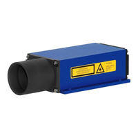
CAPI CLDM42A
ASTECH CAPI CLDM42A Manuals
Manuals and User Guides for ASTECH CAPI CLDM42A. We have
1
ASTECH CAPI CLDM42A manual available for free PDF download: Manual
ASTECH CAPI CLDM42A Manual (51 pages)
Brand:
ASTECH
| Category:
Measuring Instruments
| Size: 1 MB
Table of Contents
Table of Contents
3
General
7
Figure 1 : Measurement Principle
7
Safety Instructions
8
General Safety Instructions
8
Intended & Conforming Use
9
Nonconforming Use
9
Laser Classification
10
Electric Supply
10
Important Operating Advice
11
Technical Data
12
Mechanical Mounting Conditions
14
Figure 3 : Dimensional Drawing
14
Figure 4 : Offset against Zero-Edge
15
Electrical Connection
16
Connector Terminal
16
Interface Cable
16
Figure 5 : View of CLDM41A and CLDM42A Pole Assignments
16
Figure 6 : Interface Cable with Connector
16
Figure 7 : Interface Cable Color Codes
17
Shield and Grounding
18
Figure 8 : Isolated Mounting
18
Termination of RS232
19
Limiting Values for Voltages
19
Start up
21
Commands and Parameter
23
General
23
DT - Distance Tracking
25
DS - Distance Tracking (<7 M)
26
DW - Distance Tracking with Target Board (10 Hz)
26
DX - Distance Tracking with Target Board (50 Hz)
26
DF - Distance Measurement with External Trigger
27
DM - Distance Measurement
27
TP - Internal Temperature [°C]
27
SA - Display/Set Average Value [1
27
SD - Display/Set Display Format [D/H/S}]
28
ST - Display/Set Measure Time [0
29
AC - Display Set ALARM Center
31
AH - Display/Set ALARM Hysterese
32
AW - Display/Set ALARM Width
32
HO - Display/Set Temperature for Heating on
32
HF - Display/Set Temperature for Heating off 18
32
RB - Display/Set Distance of I = 4 Ma
33
RE - Display/Set Distance of IOUT = 20 Ma
33
Rmx y Z - Display/Set Remove Measurement
33
Tdx y - Display/Set Trigger Delay Trigger Level
34
Tmx y - Display/Set Trigger Mode Trigger Level
35
BR - Display/Set Baud Rate [2400
36
AS - Display/Set Autostart Command
36
OF - Display/Set Distance Offset
37
SO - Set Current Distance to Offset
37
LO - Laser on
37
LF - Laser off
37
PA - Display Settings
37
PR - Reset Settings
37
Figure 10 : Program Ldmtool
38
Interface Connection
39
Serial Interface RS232
39
Figure 15 : Diagram of RS232 Wiring at 9-Position D-Sub Cable Jack
39
Figure 16 : Diagram of RS232 Wiring at 25-Pole D-Sub Cable Jack
39
Serial Interface RS422
40
Output Format on the Serial Interface
40
Figure 17 : RS232 Wiring Diagram
40
Digital Switching Output (Alarm)
41
Figure 18 : Wiring Diagram of Digital Switching Output
41
Analog Output
43
Figure 20 : Wiring Diagram of Analog Output
43
Trigger Input
44
Figure 21 :Output Current Diagram for RE > RB and RE < RB
44
Figure 22 : Wiring Diagram of Trigger Input
45
List of Commands
46
Error Codes
48
PC Interface Cable (Option)
49
Figure 23 : RS232 Cable with Power Supply for CLDM41A and CLDM42A
49
EG Declaration of Conformity
50
Part Numbers
51
Advertisement
Advertisement
Related Products
ASTECH CAPI CLDM41A
ASTECH CR200E
ASTECH CR210E
ASTECH LDM41PN
ASTECH LDM42PN
ASTECH LDS11A
ASTECH VLM500-DG
ASTECH VLM500-MID
ASTECH Categories
Accessories
Measuring Instruments
Security Camera
Transmitter
Security Sensors
More ASTECH Manuals
Login
Sign In
OR
Sign in with Facebook
Sign in with Google
Upload manual
Upload from disk
Upload from URL