Sign In
Upload
Manuals
Brands
Ashcroft Manuals
Measuring Instruments
DM61
Ashcroft DM61 Manuals
Manuals and User Guides for Ashcroft DM61. We have
1
Ashcroft DM61 manual available for free PDF download: Installation And Maintenance Instructions Manual
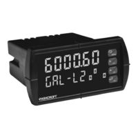
Ashcroft DM61 Installation And Maintenance Instructions Manual (100 pages)
Digital Panel Meter
Brand:
Ashcroft
| Category:
Measuring Instruments
| Size: 1 MB
Table of Contents
Table of Contents
3
Introduction
6
Ordering Information
7
Specifications
8
General
8
Process Input
10
Relays
11
Isolated 4-20 Ma Transmitter Output
12
Modbus ® RTU Serial Communications
12
Compliance Information
13
Safety
13
Electromagnetic Compatibility
13
Safety Information
14
Installation
15
Unpacking
15
Panel Mounting Instructions
15
Figure 1. 1/8 DIN Panel Cutout Dimensions
15
Figure 2. Panel Mounting Details
16
Mounting Dimensions
17
Figure 3. Meter Dimensions - Side View
17
Figure 4. Meter Dimensions - Top View
17
Configuration for 12 or 24 VDC Power Option
18
Figure 5. Jumper Configuration for 12/24 VDC Power
18
Connections
19
Figure 6. Transmitter Supply Voltage Selection
19
Connectors Labeling
20
Power Connections
20
Figure 7. Connector Labeling for Fully Loaded DM61
20
Figure 8. Power Connections
20
Signal Connections
21
Figure 9. Transmitters Powered by Internal Supply
21
Figure 10. Transmitter Powered by Ext. Supply or Self-Powered
21
Modbus RTU Serial Communications
22
Relay Connections
22
Figure 11. Voltage Input Connections
22
Figure 12. Relay Connections
22
Switching Inductive Loads
23
Figure 13. AC and DC Loads Protection
23
Figure 14. Low Voltage DC Loads Protection
23
F4 Digital Input Connections
24
4-20 Ma Output Connections
24
Analog Output Transmitter Power Supply
24
Figure 15. F4 Digital Input Connections
24
Figure 16. 4-20 Ma Output Connections
24
External Relays & Digital I/O Connections
25
Figure 17. Expansion Modules & DIN Rail Mounting Kit
25
Figure 18. External Relays Module Connections
25
Interlock Relay Feature
26
Figure 19. Digital I/O Module Connections
26
Figure 20. Interlock Connections
26
Setup and Programming
27
Front Panel Buttons and Status LED Indicators
28
Display Functions & Messages
29
Main Menu
32
Setting Numeric Values
33
Setting up the Meter (Setup)
34
Setting the Input Signal (Input)
35
Setting the Input Units or Custom Tags (Units)
36
Setting the Decimal Point (Dec Pt)
37
Programming the Meter (Prog)
38
Program Menu for Single Scale Process
38
Program Menu for Dual-Scale Level Applications
38
Multi-Point Calibration & Scaling
39
Dprom Software
39
Scaling the Meter (SCALE)
39
Dual-Scale for Level Application
40
Calibrating the Meter with External Source (Cal)
42
Setting the Display Parameter & Intensity (Dsplay)
43
Display Setup Menu
44
Setting the Relay Operation (Relay)
45
Setting the Relay Action
46
Programming Set and Reset Points
47
Setting Fail-Safe Operation
47
Programming Time Delay
47
Relay Action for Loss of 4-20 Ma Input (Loop Break)
47
Relay and Alarm Operation Diagrams
48
High Alarm Operation (Set > Reset)
48
Low Alarm Operation (Set < Reset)
49
High Alarm with Fail-Safe Operation (Set > Reset)
50
Low Alarm with Fail-Safe Operation (Set < Reset)
51
Pump Alternation Control Operation
52
Relay Sampling Operation
53
Signal Loss or Loop Break Relay Operation
54
Time Delay Operation
55
Relay Operation Details
56
Overview
56
Relays Auto Initialization
56
Fail-Safe Operation
56
Front Panel Leds
57
Latching and Non-Latching Relay Operation
57
Non-Latching Relay (Auto)
58
Non-Latching Relay (A-Man)
58
Latching Relay (Latch)
58
Latching Relay (Lt-Clr)
59
Acknowledging Relays
59
Figure 21. Acknowledge Relays W/Function Key or Digital Input
59
Pump Alternation Control Applications (Altern)
60
Setting up the Interlock Relay (Force On) Feature
63
Scaling the 4-20 Ma Analog Output (Aout)
64
Reset Menu (Reset)
65
Control Menu (Contrl)
65
Setting up the Password (Pass)
66
Protecting or Locking the Meter
66
Making Changes to a Password Protected Meter
67
Disabling Password Protection
67
Advanced Features Menu
68
Advanced Features Menu & Display Messages
69
Noise Filter (Filter)
72
Noise Filter Bypass (Bypass)
72
Rounding Feature (Round)
72
Modbus RTU Serial Communications (Serial)
73
Select Menu (Select)
74
Signal Input Conditioning (Functn)
74
Low-Flow Cutoff (Cutoff)
77
Analog Output Programming (Aoutpr)
77
Programmable Function Keys User Menu (User)
78
Tare (Tare)
79
Internal Source Calibration (ICAL)
80
Meter Copy Function (Copy)
82
Meter Operation
84
Front Panel Buttons Operation
84
Function Keys Operation
84
F4 Operation
85
Maximum/Minimum Readings
85
Troubleshooting
86
Diagnostics Menu (Diag)
86
Determining Software Version
86
Reset Meter to Factory Defaults
87
Factory Defaults & User Settings
88
Troubleshooting Tips
91
Alphabetical List of Display Functions & Messages
92
Figure 22. 1/8 DIN Panel Cutout Template
99
Advertisement
Advertisement
Related Products
Ashcroft DG25
Ashcroft D7 series
Ashcroft DP55
Ashcroft 1082
Ashcroft 2032
Ashcroft 2036
Ashcroft 2074
Ashcroft 2132
Ashcroft 2136
Ashcroft Categories
Measuring Instruments
Transmitter
Transducer
Switch
Accessories
More Ashcroft Manuals
Login
Sign In
OR
Sign in with Facebook
Sign in with Google
Upload manual
Upload from disk
Upload from URL