Sign In
Upload
Manuals
Brands
ASEM Manuals
Control Panel
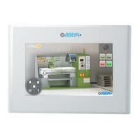
HMI30-TF
ASEM HMI30-TF Manuals
Manuals and User Guides for ASEM HMI30-TF. We have
1
ASEM HMI30-TF manual available for free PDF download: User Manual
ASEM HMI30-TF User Manual (91 pages)
Open Automation Systems
Brand:
ASEM
| Category:
Control Panel
| Size: 3 MB
Table of Contents
Table of Contents
3
Section 1
7
General Notes
8
Instructions on Disposal
8
Trademarks
8
Description of Safety Symbols
9
Basic Knowledge Required
10
Figures
10
Proper Use of the Product
10
Purpose of the User's Guide
10
Qualified Personnel
10
The Manual Is a Part of the System
10
Safety Instructions
11
Installation According to the Instructions
11
Hazardous Areas
11
Working on the Control Cabinet
11
Scope of the Operating Instructions
11
Applicable Standard
12
Notes about Usage
12
1 Preliminary Information
7
Section 2
13
2 Description
13
Product Description
14
Key Features
14
Package
14
Table 1 Package
14
Configuration
15
HMI30 (Full Aluminium Front Panel)
15
HMI30-TF (Aluminium Front Panel with True Flat Technology)
15
Figure 1 HMI30 5.7
15
Figure 2 HMI30-TF 5.7
15
Main Difference between Full Aluminium Front Panel and Aluminium Front Panel with True Flat Technology
16
Figure 3 Front Panel "Step" Detail
16
Figure 4 Front Panel "No Step" Detail
16
Front View
17
Full Aluminium Front Panel
17
Aluminium Front Panel with True Flat Technology
17
Figure 5 Full Aluminium Front Panel Detail
17
Figure 6 Aluminium Front Panel with True Flat Technology Detail
17
Widescreen
18
Figure 7 Widescreen Full Aluminium Front Panel Detail
18
Figure 8 Widescreen Aluminium Front Panel with True Flat Technology Detail
18
Rear View
19
Figure 9 HMI30 5.7" Rear View
19
Figure 10 HMI30 7.0" Rear View
19
Figure 11 HMI30 8.4" Rear View
20
Side View
21
Figure 12 HMI30 5.7" Side View
21
Figure 13 HMI30 5.7" Side View
21
Connector View
22
Labels
22
Figure 14 HMI30 5.7" Connectors
22
Figure 15 HMI30 Connectors Label Detail
22
Figure 16 HMI30 CE Label Detail
22
Touchscreen
23
Table 2 Touchscreen
23
Putting in Operation HMI30
24
Configuration and Project Creation
24
Process Management
24
Figure 17 Configuration and Project Creation
24
Figure 18 Process Management
24
Software Options
25
Table 3 Software Options
25
Table 4 Graphic Interface
25
Table 5 Alarm Log
25
Table 6 Recipes - Data Loggers
25
Table 7 Trends
25
Table 8 Users & Passwords
25
Table 9 Dynamic Multilanguage
26
Table 10 Drivers
26
Table 11 Event Object
26
Table 12 Scaling Object
26
Table 13 Scheduler Object
26
Table 14 Logics
26
Table 15 Networking
26
Table 16 Child Projects
26
Table 17 Software Options
26
Table 18 Visual Studio Source Safe 2005 Integration
26
Section 3
27
3 Installation and Connection
27
Preparation for Installation
28
Select the Mounting Location
28
Checking the Package Contents
28
Checking the Operating Conditions
28
Mounting Position
29
Damage Due to Overheating
29
Figure 19 Mounting Position
29
Checking Installation Distances
30
Preparing the Mounting Cut-Out
30
Figure 20 Installation Distances
30
Cut-Out Measures
31
Degrees of Protection
31
Figure 21 HMI30 5.7" Cut-Out
31
Figure 22 HMI30 5.7 Cut-Out
31
Figure 23 HMI30 5.7" Cut-Out
31
Figure 24 HMI30 10.4 Cut-Out
32
Figure 25 HMI30 12.1 Cut-Out
32
Figure 26 HMI30 15.0 Cut-Out
32
Mounting the Device
33
Position of the Mounting Clamps
33
Table 23 Position of the Mounting Clamps
33
Tools to Tighten the Mounting Clamps
34
Procedure
35
Figure 27 Installation
35
Figure 28 Installation
35
Figure 29 Installation
36
Figure 30 Installation
36
Figure 31 Installation
36
Figure 32 Installation
37
Figure 33 Installation
37
Connecting the Device
38
Notes on Connection
38
Grounding and Bonding
38
Power Supply Connection
38
Figure 34 Power Supply Connection Detail
38
Switching on and Testing the HMI Device
39
Figure 35 Power Supply Connection Detail
39
Figure 36 Power Supply Connection Detail
39
Connecting the Configuration PC
40
Figure 37 Connecting the Configuration PC
40
Table 24 Connecting the Configuration PC
40
Figure 38 Connecting the Configuration PC
41
Figure 39 Connecting the Configuration PC
41
Figure 40 Connecting the Configuration PC
42
Figure 41 Connecting the Configuration PC
42
Figure 42 Connecting the Configuration PC
43
Figure 43 Connecting the Configuration PC
43
Procedure
43
Figure 44 Connecting the Configuration PC
44
Table 25 Procedure
44
Section 4
45
4 Commissioning the Device
45
Backup Design
46
Internal Memory
46
Figure 45 Commissioning the Device
46
Slot for Memory Card
47
Installation/Removal of a Memory Card
47
Figure 46 Slot for Memory Card
47
Figure 47 Slot for Memory Card
47
Figure 48 Slot for Memory Card
47
Figure 49 Slot for Memory Card
48
Figure 50 Slot for Memory Card
48
Figure 51 Slot for Memory Card
48
Section 5
49
5 Commissioning a Project
49
Overview
50
Transfer
50
Configuring the Serial Port
50
Figure 52 Configuring the Serial Port
51
Figure 53 Configuring the Serial Port
51
Figure 54 Configuring the Serial Port
51
Connecting the Serial Port
52
Managing the Project
52
Figure 55 Configuring the Serial Port
52
Figure 56 Stopping the Running Project
53
Figure 57 Stopping the Running Project
53
Stopping the Running Project
53
Figure 58 Starting the Project
54
Figure 59 Starting the Project
54
Starting the Project
54
Debugging the Project
55
Figure 60 Debugging the Project
55
Figure 61 Debug the Project
56
Figure 62 Debug the Project
56
Figure 63 Debug the Project
56
Figure 64 Debug the Project
57
Trasfer the Project from HMI30 to the Configuration PC
57
Backup and Restore
58
Updating the Operating System
58
Figure 65 Debug the Project
58
Section 6
59
6 Maintenance and Care
59
Calibration of the Touchscreen
60
Figure 66 Calibration of the Touchscreen
60
Figure 67 Calibration of the Touchscreen
60
Maintaining & Cleaning
61
Figure 68 Calibration of the Touchscreen
61
Backup Battery Replacement (CR2032 3V)
62
Figure 69 Backup Battery Replacement
62
Figure 70 Backup Battery Replacement
62
Procedure
62
Figure 71 Backup Battery Replacement
63
Figure 72 Backup Battery Replacement
63
Figure 73 Backup Battery Replacement
63
Figure 74 Backup Battery Replacement
64
Figure 75 Backup Battery Replacement
64
Figure 76 Backup Battery Detail
64
Technical Support & Repairs
65
Recycling and Disposal
65
Figure 77 Backup Battery Replacement
65
Figure 78 Backup Battery Detail
65
Section 7
67
7 Technical Specifications
67
Technical Specifications
68
Table 26 System Software Characteristics
68
Table 27 System Hardware Characteristics
69
Table 28 Electrical Characteristics
69
Table 29 Mechanical Characteristics
69
Table 30 Environmental Characteristics
69
Table 31 Displays
70
Table 32 Measuraments
70
Table 33 Warranty & Approvals
70
Display Characteristics
71
Table 34 5.7" Display Characteristics
71
Table 35 7.0" Display Characteristics
71
Table 36 5.4" Display Characteristics
71
(SVGA) Display Characteristics
72
(XGA) Display Characteristics
72
Display Characteristics
72
Table 37 10.4" Display Characteristics
72
Table 38 12.1" (SVGA) Display Characteristics
72
Table 39 12.1" (XGA) Display Characteristics
72
Display Characteristics
73
Certificates and Approvals
73
Table 40 15.0" Display Characteristics
73
Dimension Drawings
74
HMI30 5.7" (Full Aluminium Front Panel)
74
Figure 79 HMI30 5.7" Front View
74
Figure 80 HMI30 5.7" Bottom View
74
Figure 81 HMI30 5.7" Side View
74
HMI30-TF 5.7" (Aluminium Front Panel with True Flat Technology)
75
Figure 82 HMI30-TF 5.7" Front View
75
Figure 83 HMI30-TF 5.7" Bottom View
75
Figure 84 HMI30-TF 5.7" Side View
75
HMI30 7.0" (Wide Full Aluminium Front Panel)
76
Figure 85 HMI30 7.0" Front View
76
Figure 86 HMI30 7.0" Bottom View
76
Figure 87 HMI30 7.0" Side View
76
HMI30-TF 7.0" (Wide Aluminium Front Panel with True Flat Technology)
77
Figure 88 HMI-TF30 7.0" Front View
77
Figure 89 HMI30-TF 7.0" Bottom View
77
Figure 90 HMI30-TF 7.0" Side View
77
HMI30 8.4" (Full Aluminium Front Panel)
78
Figure 91 HMI30 8.4" Front View
78
Figure 92 HMI30 8.4" Bottom View
78
Figure 93 HMI30 8.4" Side View
78
HMI30-TF 8.4" (Aluminium Front Panel with True Flat Technology)
79
Figure 94 HMI30-TF 8.4" Front View
79
Figure 95 HMI30-TF 8.4" Bottom View
79
Figure 96 HMI30-TF 8.4" Side View
79
HMI30 10.4" (Full Aluminium Front Panel)
80
Figure 97 HMI30 10.4" Front View
80
Figure 98 HMI30 10.4" Bottom View
80
Figure 99 HMI30 10.4" Side View
80
HMI30-TF 10.4" (Aluminium Front Panel with True Flat Technology)
81
Figure 100 HMI30-TF 10.4" Front View
81
Figure 101 HMI30-TF 10.4" Bottom View
81
Figure 102 HMI30-TF 10.4" Side View
81
HMI30 12.1" (Wide Full Aluminium Front Panel)
82
Figure 103 HMI30 12.1" Front View
82
Figure 104 HMI30 12.1" Bottom View
82
Figure 105 HMI30 12.1" Side View
82
HMI30-TF 12.1" (Wide Aluminium Front Panel with True Flat Technology)
83
Figure 106 HMI-TF30 12.1" Front View
83
Figure 107 HMI30-TF 12.1" Bottom View
83
Figure 108 HMI30-TF 12.1" Side View
83
HMI30 15.0" (Full Aluminium Front Panel)
84
Figure 109 HMI30 15.0" Front View
84
Figure 110 HMI30 15.0" Bottom View
84
Figure 111 HMI30 15.0" Side View
84
HMI30-TF 15.0" (Aluminium Front Panel with True Flat Technology)
85
Figure 112 HMI30-TF 15.0" Front View
85
Figure 113 HMI30-TF 15.0" Bottom View
85
Figure 114 HMI30-TF 15.0" Side View
85
Ports PINOUT
86
COM1 - DB15M Serial
86
Lan1 - Lan2
86
Table 41 COM1 - DB15M Serial
86
Table 42 LAN1 - LAN2
86
Usb1 / Usb2
87
Technical Support & Repairs
87
Table 43 USB1 - USB2
89
Advertisement
Advertisement
Related Products
ASEM HMI30
ASEM Categories
Network Router
Desktop
Motherboard
Touch terminals
Control Panel
More ASEM Manuals
Login
Sign In
OR
Sign in with Facebook
Sign in with Google
Upload manual
Upload from disk
Upload from URL