Sign In
Upload
Manuals
Brands
ASELSAN Manuals
Measuring Instruments
STC-8250A
ASELSAN STC-8250A Manuals
Manuals and User Guides for ASELSAN STC-8250A. We have
2
ASELSAN STC-8250A manuals available for free PDF download: Operation Manuals, Preparation Manual
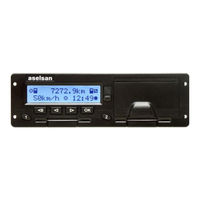
ASELSAN STC-8250A Preparation Manual (113 pages)
Digital Tachograph
Brand:
ASELSAN
| Category:
Recording Equipment
| Size: 5 MB
Table of Contents
Table of Contents
2
1 Safety
8
2 Introduction
10
General
10
Copyright
10
Notational Conventions
11
Legal Requirements
12
Workshop Responsibilities
12
Tachograph Version
12
3 Tachograph System Overview
13
Motion Sensor
13
Digital Tachograph
13
Display in Instrument Cluster
14
Tachograph Cards
14
Driver Cards
14
Company Cards
14
Control Cards
14
Workshop Cards
15
4 Preparation of the Operational Environment
15
Security Objectives for the Operational Environment
15
Oe.activation
15
Oe.approved_Workshops
15
Oe.faithful_Calibration
16
Oe.card_Availability
16
Oe.card_ Traceability
16
OE. Controls
16
Oe.driver_Card_Uniqueness
16
Oe.faithful_Drivers
16
Oe.regular_Inspections
17
Oe.type_Approved_Ms
17
5 Workshop Interaction
18
Front Panel
18
Back Panel
19
Display
19
Display Modes
19
Default Display (Speed & Odometer) (#1)
20
Current Work Periods and Activities for Driver and Co-Driver (#2)
20
Weekly Remaining Driving Time for Driver 1 (#3)
21
Daily Remaining Driving and Rest Times for Driver 1 (#4)
21
Driving Times for Driver 1 (#5)
21
Driving Times for Driver 2. (#6)
22
Driver and Co-Driver Activities and Local Time (#7)
22
UTC Time (#8)
22
Special Displays
23
Activation Status
23
Out of Scope
23
Ferry Transfer / Train Crossing
23
Keypad
23
Card Slots
24
Printer
24
Paper Roll
25
Service (Calibration and Data Download) Interface (6-Pin)
25
Vehicle Dashboard Integration
26
Acoustic Warnings
26
Pictograms
26
6 Mode of Operations
27
Operational Mode
27
Company Mode
27
Control Mode
28
Calibration Mode
28
PIN Entering
28
Calibration
29
7 Menu Structure
29
List of Figures
33
Checking before Installation
32
General Instructions Prior to Installation
32
Receipt of Device
32
Storage
32
Details of the Descriptive Label and Visual Checks
33
Figure 8-1: Showing the Descriptive Label of STC-8250
33
Figure 8-2: Showing the Plastic Melted over the Grabbers to Hold the Grabber
34
Visual Checks
34
Figure 8-3: Showing the Seals on the Top of the VU Which Is Located on the Battery Cover
35
Figure 8-4: Showing the Seal Backside of the STC-8250 Which Is Located on the Connector
35
List of Tables
39
Figure 8-5: Showing the Warranty Sticker Which Is Placed at the Backside
36
Installation Operations
36
Tools and Equipment Needed
36
Cabling
37
Installation of Digital Tachograph
37
Motion Sensor
37
Sensor Cable
37
Connector Panel
38
Figure 9-1: Wiring Diagram of STC-8250 in Vehicle
38
Power Connections
38
Figure 9-2: Showing the Rear Connector Panel Pin Allocation
39
Pin Assignments
39
Table 9-1: Pin Assignment for Connector-A
39
Table 9-2: Pin Assignment for Connector-B
40
Table 9-3: Pin Assignment for Connector-C
40
Table 9-4: Pin Assignment for Connector-D
40
Activation and Motion Sensor Pairing
41
Mounting the Tachograph
41
Calibration
43
Checking Calibration Data
44
Sealing
45
Test Drive
45
Installation Plaque
46
Display Backlight Level
47
General Settings
47
Language
47
Local Time
48
UTC Correction
48
Backlight Test
49
Built-In Tests
49
Service Menu (Parameter Configuration)
49
Dead Pixel Test
50
Keypad Test
51
Printer Test
51
Battery Level
52
Card Reader Test
53
Data Integrity Test
53
Data Download Test
54
Buzzer Test
55
Software Integrity Test
55
Backlight
56
Configuration
56
General Configurations
56
Military Dimmer
57
LCD Distance Unit
58
Activity Ignition off
59
Activity Ignition on
59
Language Change
60
Calibration Due Date Warning
61
Driver Card Expiration Date Warning
61
Warning Expiration Date
61
Workshop Card Expiration Date Warning
62
Company Card Expiration Date Warning
63
Control Card Expiration Date Warning
63
Overspeed Pre-Warning out
64
Overspeed Pre-Warning Time
64
B7 Recognize
65
Baud Rate
66
CAN Configurations
66
CAN-A Configurations
66
Sample
67
Synchronous Jump
67
CAN Services
68
CAN-C Configurations
68
IMS Source
68
Overspeed TCO1
69
Heartbeat Monitoring
70
Trip-Meter Reset
70
Output Shaft Speed
71
TCO1 Period
71
TCO1 Handling Info
72
TCO1 Priority
72
Ims Can
73
CAN Protocols
74
Inspecting Procedure
75
Inspection
75
Visual Inspection
75
Calibration
76
Certification
76
Faulty Unit
76
Downloading Vehicle Stored Data
77
Figure 12-1: Showing the Tachograph Removal Process
77
Removal of the Digital Tachograph
77
Battery Replacement Procedure of the STC-8250
79
Figure 12-2: Showing the Battery Cover and Its Seals
80
Messages, Warning and Faults
82
Table 13-1: List of Message
82
Table 13-2: List of Pre-Warnings
84
Table 13-3: List of Warnings
85
Table 13-4: List of Faults
88
Diagnostic Trouble Codes (Dtcs)
91
Table 14-1: List of Diagnostic Trouble Codes (Dtcs)
91
Care and Maintenance
93
Care of the Cards
93
Care of the Tachograph
93
Software & Hardware Information
93
Upgrading the STC-8250 Operating Software
94
Table 18-1: Technical Data
96
Technical Data
96
National / Regional Abbreviations and European Time Zones
97
Table 19-1: Country Codes
97
Pictogram Combinations
99
Region Abbreviations of Spain
99
Table 19-2: Regions of Spain
99
Table 20-1: Pictogram Combinations
99
Driver Card Printout
101
Sample Printouts
101
Driver Card Printout Continued
102
Vehicle Unit Printout
103
Vehicle Unit Printout Continued
104
Events & Faults Vehicle Unit Printout
105
Events & Faults Vehicle Unit
106
Printout Continued
106
Detailed View of Events & Faults VU Printout
107
List of Figures
111
Advertisement
ASELSAN STC-8250A Operation Manuals (122 pages)
Digital Tachograph
Brand:
ASELSAN
| Category:
Measuring Instruments
| Size: 3 MB
Table of Contents
Table of Contents
3
Safety
8
Introduction
10
General
10
Notational Conventions
11
Legal Requirements
12
Driver Responsibilities
12
Company Responsibilities
12
Tachograph Version
13
Copyright
13
Configuration
14
Getting Started
15
For the Driver and Co-Driver
15
For the Company
16
Preparation of the Operational Environment
17
Security Objectives for the Operational Environment
17
Oe.activation
17
Oe.approved_Workshops
17
Oe.faithful_Calibration
17
Oe.card_Availability
17
Oe.regular_Inspections
18
Oe.card_ Traceability
18
OE. Controls
18
Oe.driver_Card_Uniqueness
18
Oe.faithful_Drivers
18
Oe.type_Approved_Ms
19
General Look
20
Front Panel
20
User Interaction
21
Display
21
Display Modes
21
Default Display (Speed & Odometer) (#1)
21
Current Work Periods and Activities for Driver and Co-Driver (#2)
22
Weekly Remaining Driving Time for Driver 1 (#3)
23
Daily Remaining Driving and Rest Times for Driver 1 (#4)
23
Driving Times for Driver 1 (#5)
24
Driving Times for Driver 2. (#6)
24
Driver and Co-Driver Activities and Local Time (#7)
24
UTC Time (#8)
25
Special Displays
25
Activation Status
25
Out of Scope
25
Ferry Transfer / Train Crossing
26
Basic Display Symbols
26
Using the Keypad
27
Card Slots
27
Printer
28
Paper Roll
28
Service (Calibration and Data Download) Interface (6-Pin)
29
Vehicle Dashboard Integration
29
Menu Tree
30
Inserting Driver and Co-Driver Cards
32
Operation of Modes
32
Operational (Driver and Co-Driver) Mode (Role)
32
Manual Entries
33
Setting Activities
37
Begin and End Place
39
Ferry or Train Condition
40
Out of Scope Condition
40
Downloading Driver Card Data
41
Displaying Card Data
43
Printing Card Data
44
Acknowledge Event or Fault Messages
45
Messages, Warnings and Faults of Operational Mode
45
Acoustic Alerts
53
Withdrawing Driver Card and Co-Driver Cards
53
Driver/Vehicle Change During Operation
54
Power Saving Mode
55
Company Mode (Role)
55
Company Inspection
55
Workshop Inspection
56
Functions of the Company Card
56
Registration of the Company (Lock-In)
57
Entering Vehicle Registration Number
58
Automatic Setting of Activity after Ignition OFF/ON
59
Ignition off Activities for Drivers
59
Igniton on Activities for Drivers
60
Downloading Mass Storage (Vehicle Data)
60
Downloading Card Data
62
Displaying and Printing Driver Card and Vehicle Data
62
De-Registration of the Company (Lock-Out)
62
Acknowledge Event or Fault Messages
64
Messages, Warnings and Faults of Company Mode/Role
64
Acoustic Alerts
72
Control Mode (Controller Role)
72
Displaying Stored and Card Data
72
Printing Stored Data
74
Downloading Vehicle Stored and Card Data
76
Acknowledge Event or Fault Messages
77
Messages, Warnings and Faults of Control Mode/Role
77
Acoustic Alerts
84
Calibration Mode (Workshop Role)
84
PIN Entering
85
Calibration
85
Built-In Test
86
Test Drive
86
Displaying Vehicle Stored and Card Data
86
Printing Vehicle Stored and Card Data
86
Downloading Vehicle Stored and Card Data
86
Messages, Warnings and Faults of Calibration Mode
86
Acoustic Alerts
92
Unknown Equipment
92
Motion Sensor
92
Unknown User (Role)
93
Messages, Warnings and Faults of Unknown Role
93
Acoustic Alerts
101
General Settings
101
Language
101
Display Backlight Level
102
Local Time
102
UTC Correction
103
Pictogram Combinations
104
Sample Printouts
106
24H Driver Card Printout
106
Driver Card Printout Continued
107
24H Vehicle Unit Printout
108
Events & Faults Vehicle
110
Detailed View of Events & Faults VU Printout
112
Events & Faults Card Printout
113
Overspeeding Printout
114
Technical Data Printout
115
Software Information
116
National / Regional Abbreviations and European Time Zones
117
Warnings about Tachograph Usage
119
Care of Tachograph
119
Care of Cards
119
Warranty and Producer Information
120
Document Revision History
121
Advertisement
Related Products
ASELSAN Categories
Recording Equipment
Radio
Measuring Instruments
More ASELSAN Manuals
Login
Sign In
OR
Sign in with Facebook
Sign in with Google
Upload manual
Upload from disk
Upload from URL