Sign In
Upload
Manuals
Brands
Aradex Manuals
Media Converter
VECTOPOWER VP5000-DC
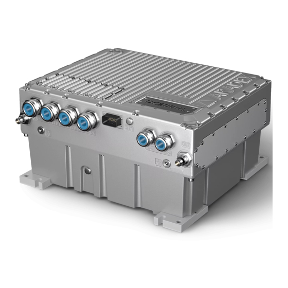
Aradex VECTOPOWER VP5000-DC Manuals
Manuals and User Guides for Aradex VECTOPOWER VP5000-DC. We have
1
Aradex VECTOPOWER VP5000-DC manual available for free PDF download: Installation Manual
Aradex VECTOPOWER VP5000-DC Installation Manual (173 pages)
Brand:
Aradex
| Category:
Media Converter
| Size: 6 MB
Table of Contents
Table of Contents
3
Installation Manual
1
Table of Contents
3
Objective of the Manual
7
Table 55: Document History
7
Table 1: Types and Article Numbers to Which this Manual Applies
7
About the Manual
7
Language of the Original Manual
7
Document History
7
Validity of the Manual for the Following Devices
7
Other Applicable Documents and Software
8
Conventions in this Manual
8
Table 2: Additionally Required Documents and Software
8
Applicable Standards and Directives
9
Copyright, Brand Names
9
Table 3: Applicable Standards and Directives
9
Safety
10
Proper Use
10
This Manual Is Part of the Device
10
Legibility of Signs and Inscriptions on the Device
10
Structure of the Safety Instructions
11
Used Symbols
12
Hazards
12
Electricity
12
Weight
13
Operating Noises
13
Hot Surfaces
13
Residual Electrical Voltage after Switch-Off
13
Coolant
14
Personnel Requirements
14
Qualified Electrician
14
Sobriety Is a Prerequisite
15
Warehouse Clerk
15
Carrier
15
Installer
15
Programmer
15
Product Description
16
Identification
16
Device Designation
16
Figure 1: Article Numbers of the VECTOPOWER
16
Rating Plate
17
Figure 2: VECTOPOWER Rating Plate
17
Figure 4: VECTOPOWER VP5000-DC/DC60 Diagram
18
Figure 3: Specification of the Hardware Version on the Rating Plate
18
Structure and Function of the VECTOPOWER VP5000-DC/DC60
18
Functional Description
18
General Function
18
Figure 5: VECTOPOWER VP5000-DC/DC200-HL Diagram
20
Structure and Function of the VECTOPOWER VP5000-DC/DC200-HL
20
Figure 6: Schematic Diagram of Precharging Contactor (4A) and Main Contactor (4B)
22
Operating Modes: Buck Converter / Boost Converter
23
Figure 7: Application Example: Boost Converter Operating Mode
23
Figure 8: Application Example: Buck Converter Operating Mode
24
Technical Data
25
Electrical Data - Power Connections
25
Electrical Data for Operation as a Buck Converter
25
Table 4: Electrical Data - Power Connections
25
Electrical Data for Operation as a Boost Converter
27
Table 5: Electrical Values for Operation as a Buck Converter
27
Electrical Data - Voltage Ripple
29
Electrical Data - [ST1] - [ST4] Logical Connections
29
Table 6: Electrical Values for Use as a Boost Converter
29
Table 7: Electrical Data - Voltage Ripple
29
Table 8: Electrical Data - General Data for [ST] - [ST4] Logical Connections
29
Table 12: Electrical Data - Digital Output 1 and 2 to [ST1]
30
Table 11: Electrical Data - [ST1]: Digital Input
30
Table 9: Electrical Data - [ST1]: Analog Voltage Input
30
Table 10: Electrical Data - [ST1]: Analog Current Input
30
Interfaces
31
General Data and Environmental Data
31
Table 13: Electrical Data - Digital Output 5 and 6 to [ST2]
31
Table 14: Interfaces
31
Data for Cooling
32
Table 15: General Data and Environmental Data
32
Table 16: Data for Cooling
32
Installation Dimensions and Distances
33
Figure 9: Cooling System Pressure Drop
33
Figure 11: Side View of the VECTOPOWER VP5000-DC/DC60 with Cooling Connections
34
Dimensions of the VECTOPOWER VP5000-DC/DC60
34
Figure 10: Top View of the VECTOPOWER VP5000-DC/DC60
34
Dimensions of the VECTOPOWER VP5000-DC/DC200-HL
35
Figure 12: Front View of the VECTOPOWER VP5000-DC/DC60 with Power and Logical Connections
35
Figure 13: Top View of the VECTOPOWER VP5000-DC/DC200-HL
35
Figure 14: Side View of the VECTOPOWER VP5000-DC/DC200-HL with Cooling Connections
36
Figure 15: Front View of the VECTOPOWER VP5000-DC/DC200-HL with Power and Logical Connections
36
Minimum Distances from Neighboring Components to be Observed
37
Figure 16: Minimum Distances, VECTOPOWER Front View
38
Figure 17: Minimum Distances, VECTOPOWER Side View
38
Table 17: Minimum Distances from Neighboring Components
39
Position and Designations of the Power, Signal, and Cooling Connections
39
Installation Position
39
Figure 18: Power and Logical Connections of the VECTOPOWER VP5000-DC/DC60
40
Table 18: Designation of the Power, Signal, and Cooling Connections of the VECTOPOWER VP5000
40
Vectopower Vp5000-DC/Dc60
40
Vectopower Vp5000-DC/Dc200-Hl
41
Figure 19: Power and Logical Connections of the VECTOPOWER VP5000-DC/DC200-HL
41
Table 19: Designation of the Power, Signal, and Cooling Connections of the VECTOPOWER VP5000
41
Vectopower Vp5000-DC/Dc200-Hl
42
Table 20: Power Connections for the VECTOPOWER VP5000-DC/DC60
42
Vectopower Vp5000-DC/Dc60
42
Power Connections
42
Wire Cross-Section of the Ground Wire Acc. to en 62477-1
43
Table of EMC Cable Glands from Pflitsch, Blueglobe TRI Type
43
Table 21: Power Connections for the VECTOPOWER VP5000-DC/DC200-HL
43
Table 22: Cross-Section of the Ground Wire Acc. to 62477-1
43
Logical Connections
44
Table 23: Data on EMC Cable Gland from Pflitsch, Blueglobe TRI Type
44
ST1] Design and Pin Assignment
45
Figure 20: Pin Assignment [ST1]
45
Table 24: Pin Assignment [ST1]
46
Figure 21: Pin Assignment [ST2]
47
ST2] Design and Pin Assignment
47
Figure 22: Pin Assignment [ST3]
49
Table 25: Pin Assignment [ST2]
49
ST3] Design and Pin Assignment
49
Table 26: Pin Assignment [ST3]
50
ST4] Design and Pin Assignment of the VECTOPOWER VP5000-DC/DC60
51
Figure 23: Pin Assignment [ST4]
51
Table 27: Pin Assignment [ST4]
51
Design of the Connections
52
Required Connections (Minimum Configuration)
52
Table 28: Required Connections (Minimum Configuration)
52
Figure 26: Minimum Configuration of the VECTOPOWER VP5000-DC/DC60 Variant with VECTOBUS
53
Figure 24: Minimum Configuration of the VECTOPOWER VP5000-DC/DC60 Variant with CAN Bus and
53
Figure 25: Minimum Configuration of the VECTOPOWER VP5000-DC/DC60 Variant with RS-232 Interface
53
Figure 27: Minimum Configuration of the VECTOPOWER VP5000-DC/DC200-HL Variant with CAN Bus
54
Figure 28: Minimum Configuration of the VECTOPOWER VP5000-DC/DC200-HL with RS-232 Interface Variant
54
Figure 29: Minimum Configuration of the VECTOPOWER VP5000-DC/DC200-HL with VECTOBUS Variant
54
ST1] and [ST2] Version of the Digital Inputs Designed as Low-Active Input
55
ST1] Digital Outputs Designed as Low-Side Switches
55
Figure 30: [ST1] and [ST2] Digital Inputs Implemented as a Low-Active Input
55
Figure 31: Design of the Digital Outputs [ST1] as Low-Side Switches
55
ST2] and [ST4] Connections for an External Precharging Circuit for VECTOPOWER VP5000- DC/DC60
56
ST2] Digital Outputs Designed as Low-Side Switches
56
Figure 32: Design of the Digital Outputs [ST2] as Low-Side Switches
56
Figure 33: Schematic Diagram of the Precharging Contactor (A) and the Main Contactor (B)
57
Figure 34: Connections of the Precharging Contactor and the Main Contactor to [ST2]
58
Table 29: Logical Connections [ST2] for the External Precharging Circuit for the VECTOPOWER VP5000
58
Table 30: Logical Connection [ST4] for the VECTOPOWER VP5000-DC/DC60
58
ST1] Connections for a Firmware Update
59
ST3] Connections to a VECTOBUS System
59
Figure 35: Example of an External Precharging Circuit of the VECTOPOWER VP5000-DC/DC60 at [OUTPUT+/-]
59
Figure 36: Wiring Diagram for a VECTOBUS System [ST3]
60
Vectopower Vp5000-DC/Dc60
60
Characteristic Curves for Current, Voltage, and Power
60
Figure 37: DC Current Characteristic Curve as a Function of the Output Voltage for VP5000-DC/DC60
61
Vectopower Vp5000-DC/Dc200-Hl
62
Figure 38: Output Power Characteristic Curve as a Function of the Output Voltage for VP5000-DC/DC60
62
Figure 39: DC Current Characteristic Curve as a Function of the Output Voltage for VP5000-DC/DC200-HL
63
Characteristic Curves for Derating
64
Vectopower Vp5000-DC/Dc60
64
Figure 41: Derating Characteristic Curve at 450 V for VP5000-DC/DC60
64
Figure 42: Derating Characteristic Curve at 650 V for VP5000-DC/DC60
64
Figure 44: Derating Characteristic Curve at 650 V for VP5000-DC/DC200-HL
65
Figure 43: Derating Characteristic Curve at 450 V for VP5000-DC/DC200-HL
65
3.10.2 Vectopower Vp5000-DC/Dc200-Hl
65
Characteristic Curves for Efficiency
66
Figure 45: Derating Characteristic Curve at 750 V for VP5000-DC/DC200-HL
66
Vectopower Vp5000-DC/Dc60
67
Figure 46: Efficiency Characteristic Curve at 100 V DC at [OUTPUT+/-] for VP5000-DC/DC60
67
Figure 47: Efficiency Characteristic Curve at 200 V DC at [OUTPUT+/-] for VP5000-DC/DC60
67
Figure 48: Efficiency Characteristic Curve at 300 V DC at [OUTPUT+/-] for VP5000-DC/DC60
68
Figure 49: Efficiency Characteristic Curve at 400 V DC at [OUTPUT+/-] for VP5000-DC/DC60
68
Figure 51: Efficiency Characteristic Curve at 100 V DC at [OUTPUT+/-] for VP5000-DC/DC200-HL
69
Figure 50: Efficiency Characteristic Curve at 500 V DC at [OUTPUT+/-] for VP5000-DC/DC60
69
Vectopower Vp5000-DC/Dc200-Hl
69
Figure 52: Efficiency Characteristic Curve at 200 V DC at [OUTPUT+/-] for VP5000-DC/DC200-HL
70
Figure 53: Efficiency Characteristic Curve at 300 V DC at [OUTPUT+/-] for VP5000-DC/DC200-HL
70
Figure 54: Efficiency Characteristic Curve at 400 V DC at [OUTPUT+/-] for VP5000-DC/DC200-HL
71
Figure 55: Efficiency Characteristic Curve at 500 V DC at [OUTPUT+/-] for VP5000-DC/DC200-HL
71
Scope of Supply
72
Accessories that Can be Obtained from ARADEX AG
72
Table 31: VECTOPOWER Scope of Delivery
72
Overview of the Required Quantities
73
Table 32: Required Accessories for VECTOPOWER
73
Figure 56: Mating Connectors for [ST1]; Source: te
74
Table 33: Specification of the Mating Connector for [ST1]
74
EMC Cable Glands [DC+/-], [OUTPUT+/-], [BR+/-]
74
Mating Connectors for [ST1]
74
Cable Lugs for [DC+/-], [OUTPUT+/-], [BR+-/], Ground Wires, and Nord-Lock Lock Washers
74
Mating Connectors for [ST2] and [ST3]
75
Figure 57: Mating Connectors for [ST2] and [ST3]; Source: Intercontec
75
Table 34: Specification of the Crimping Pliers for [ST1]
75
Table 35: Specification of the Mating Connectors for [ST2] and [ST3]
75
Table 36: Specification of the Crimping Pliers for [ST2] and [ST3]
75
Table 38: Specification of the Crimping Pliers for [ST4]
76
Table 37: Specification of the Mating Connector for [ST4]
76
Figure 58: Mating Connector for [ST4]; Source: Intercontec
76
Cooling Water Connection
76
Mating Connector for [ST4]
76
Connection Interface
77
Other Accessories
77
Accessories that the Customer Must Provide
77
Cables/Wires and Terminals (Specification)
77
Table 39: Specification of USB - RS-232 or CAN Bus Connection Cable
77
Wire for [DC+/-], [OUTPUT+/-], And, if Required, [BR+/-]
78
Cable for [ST1]
78
Table 40: Specification of the Cables for the Crimp Contacts for [ST1]
78
Table 41: Specification of the Cable for the Crimp Contacts for [ST2] and [ST3]
79
Cable for [ST4]
79
Cables for [ST2] and [ST3]
79
Table 42: Specifications of the Cables for the Crimp Contacts for [ST4]
80
Notes on Planning
81
Qualification of the Planner
81
Checklist for System Integration of the VECTOPOWER
81
Notes on System Integration
83
Observing Standards, Directives, and Statutory Provisions
83
Selection: Observe the Derating
83
Minimizing Residual Risks
83
Table 43: Checklist for System Integration
83
Providing Adequate Cooling
84
Considering Project Planning Scenarios
84
Providing Secure Fastening
84
Allowing Sufficient Space
84
Application of a Higher Voltage to [DC+/-]
85
Providing a Device or Method to Make Sure that no Voltage Is Present
85
Protecting Connections Externally
85
Optionally Integrating [ST4] with VECTOPOWER VP5000-DC/DC60
85
Integrating a Brake Chopper [BR+/-] with VECTOPOWER VP5000-DC/DC200-HL
86
Providing a Precharging Circuit with the VECTOPOWER VP5000-DC/DC60
87
Figure 59: Schematic Diagram of the Precharging Contactor (A) and the Main Contactor (B)
88
Figure 60: Example of an External VECTOPOWER Precharging Circuit at [DC+/-]
88
Providing a Precharging Circuit for VECTOPOWER VP5000-DC/DC200-HL
89
Figure 61: Example of an External VECTOPOWER Precharging Circuit at [DC+/-]
89
Protection against Large Currents When Switching on
90
Measuring Current Ripple and Voltage Ripple
91
Using External Capacitors and Chokes to Attenuate the Voltage Ripple and Current Ripple
91
Ensuring Electromagnetic Compatibility (EMC)
93
Figure 62: Example of Electrolytic Capacitors Connected in Series with Symmetry Resistors Connected in
93
Use of y Capacitors in the DC Link [DC+/-]
94
Transport
95
Qualification of Personnel
95
Packaging
95
Packaging, Transport, Storage
95
Transport Lock
96
Storage
96
Installation and Commissioning
97
Qualification of Personnel
97
Receipt
97
Installation
97
Mounting on a Vertical Mounting Plate
97
Figure 65: Mounting Points on the Housing of the VECTOPOWER VP5000-DC/DC60
99
Figure 64: Crane Eyes on the Housing of the VECTOPOWER VP5000-DC/DC200-HL
99
Figure 63: Crane Eyes on the Housing of the VECTOPOWER VP5000-DC/DC60
99
Mounting on a Horizontal Mounting Plate
100
Figure 66: Mounting Points on the Housing of the VECTOPOWER VP5000-DC/DC200-HL
100
Figure 67: Crane Eyes on the Housing of the VECTOPOWER VP5000-DC/DC60
102
Figure 68: Crane Eyes on the Housing of the VECTOPOWER VP5000-DC/DC200-HL
102
Figure 69: Mounting Points on the Housing of the VECTOPOWER VP5000-DC/DC60
102
Figure 70: Mounting Points on the Housing of the VECTOPOWER VP5000-DC/DC200-HL
103
Connect the Cooling Unit
104
Figure 71: Cooling Connections of the VECTOPOWER VP5000-DC/DC60
104
Figure 72: Cooling Connections of the VECTOPOWER VP5000-DC/DC200-HL
104
Preparing the [DC+/-], [OUTPUT+/-], And, if Necessary, [BR+/-] Wires for Power Connections
105
Figure 73: Position of the Support Surface for the EMC Cable Gland on the Cable Shield
106
Figure 74: Connection Dimensions for Power Wire
106
Figure 75: Wire Stripping
108
Figure 76: Mounting the Cable Lug
108
Figure 77: Crimping the Cable Lug
109
Figure 78: Applying Shrink Tubing
109
Figure 79: Example of Globe Sealing Insert, Pflitsch, Blueglobe TRI Type Shown
110
Figure 80: Example: Plugging on an EMC Cable Gland (Pflitsch, Blueglobe TRI Type)
110
Preparing the [ST1] Cable
112
Figure 81: Assembly Manual for [ST1] AMPSEAL Series 770680 Mating Connector, Pages 1+2, Source: te
114
Preparing the [ST2] and [ST3] Cable
115
Figure 82: Assembly Manual for [ST2] and [ST3] Mating Connectors Series 623, Connector Crown Clamp, for
116
ST4] Cable Preparation for VECTOPOWER VP5000-DC/DC60
117
Figure 83: Assembly Manual for [ST4] Mating Connector Series 923, Connector Crown Clamping, for Crimp
118
Establishing Electrical Connections on the VECTOPOWER VP5000-DC/DC60
119
Figure 84: Position of the Electrical Connections on the VECTOPOWER VP5000-DC/DC60
119
Table 44: Tightening Torques of the Housing Cover Screw Fitting
119
Table 45: Tightening Torques of Cable Lug Screw Fittings
119
Table 46: Tightening Torques of EMC Cable Glands from Pflitsch, Blueglobe TRI Type
120
Figure 86: Example of a Screwed-In Double Nipple with Spring (Pflitsch, Blueglobe TRI Type)
122
Figure 85: Example of Double Nipple from Pflitsch, Blueglobe TRI Type
122
Figure 87: Covers on the VECTOPOWER VP5000-DC/DC60
123
Figure 88: [DC+/-] and [OUTPUT+/-] Connections on the VECTOPOWER VP5000-DC/DC60
123
Figure 89: Connection of a Power Wire to the Terminal Block
123
Figure 91: Example of EMC Cable Gland (Pflitsch, Blueglobe TRI Type)
124
Figure 92: Covers on the VECTOPOWER VP5000-DC/DC60
125
Figure 93: Logical Connections on the VECTOPOWER VP5000-DC/DC60
125
Establishing Electrical Connections on the VECTOPOWER VP5000-DC/DC200-HL
126
Figure 95: Position of All Electrical Connections on the VECTOPOWER VP5000-DC/DC200-HL
126
Table 47: Tightening Torques of the Housing Cover Screw Fitting
126
Table 49: Tightening Torques of EMC Cable Glands from Pflitsch, Blueglobe TRI Type
127
Table 48: Tightening Torques of Cable Lug Screw Fittings
127
Figure 96: Example of Double Nipple from Pflitsch, Blueglobe TRI Type
129
Figure 97: Example of a Screwed-In Double Nipple with Spring (Pflitsch, Blueglobe TRI Type)
129
Figure 98: Covers on the VECTOPOWER VP5000-DC/DC200-HL
129
Figure 99: [DC+/-] and [OUTPUT+/-] Connections on the VECTOPOWER VP5000-DC/DC200-HL
130
Figure 100: Connection of a Power Wire to the Terminal Block
130
Figure 101: Installation Examples: Screw Connections with Wedge Lock Washer, Source: Nord-Lock Data
130
Figure 102: Example of EMC Cable Gland (Pflitsch, Blueglobe TRI Type)
130
Figure 103: [BR+/-] Connections on the VECTOPOWER VP5000-DC/DC200-HL
131
Figure 106: Ground Wire Connection on the Outside of the Housing
132
Figure 105: Example for the Logical Connections
132
Figure 104: Covers on the VECTOPOWER VP5000-DC/DC200-HL
132
Commissioning
133
Test System for Testing
133
Tests before Initial Commissioning
133
Initial Commissioning for an Application
135
Table 50: Checklist for Testing before Initial Commissioning
135
Figure 107: Veconfig: Display of the CAN Bus Networks
137
Initial Commissioning with an Existing Parameter Set
138
Figure 108: Veconfig: Display of the CAN Bus Networks
140
Commissioning for a Series Application
141
Forming after Storage for more than 6 Months
143
Preparing Forming
144
Table 51: Required Parts and Devices for Forming
144
Figure 109: Design of the Circuit for VECTOPOWER VP5000-DC/DC60
144
Figure 110: Design of the Circuit for VECTOPOWER VP5000-DC/DC200-HL
144
Performing the Forming
145
Figure 111: Schematic Sequence for Forming
146
Operation
147
Qualification of Personnel
147
Switching on and off
147
Cleaning
147
Control
147
Inspection and Maintenance
148
Daily Visual Inspection
149
Annual Maintenance
149
Maintenance Work: Checking the Ground Wire System
149
Table 52: Daily Visual Inspection
149
Table 53: Annual Maintenance
149
Behavior in the Event of Faults
150
Fault Rectification Procedure
150
Fault Rectification
150
Maintenance Work: Checking the Coolant
150
Maintenance Work: Checking Cooling Connections
150
Maintenance Work: Checking Electrical Connections
150
Checklist for Malfunctions
152
Table 54: Checklist of Malfunctions
152
Visible Damage
153
Problems with Firmware
153
Maintenance and Repair
155
Qualification of Personnel
155
Spare Parts and Repair
155
Commissioning after Maintenance and Repair
155
Decommissioning
156
Qualification of Personnel
156
Disassembly and Disposal
158
Qualification of Personnel
158
Removing the Device
158
Disposing of Recyclable Materials
159
Glossary
160
Document History
163
List of Figures
164
List of Tables
167
Index
169
Advertisement
Advertisement
Related Products
Aradex VECTOPOWER VP5000-DC60
Aradex VECTOPOWER VP5000-DC200-HL
Aradex VECTOPOWER VP600 Series
Aradex VECTOPOWER VP600-17W040-61.1.00.14.00
Aradex VECTOPOWER VP600-17W040-61.1.04.24.00
Aradex VECTOPOWER VP600-18W140-61.1.20.14.00
Aradex VECTOPOWER VP600-18W160-61.1.22.14.00
Aradex VECTOPOWER VP600-18X160-21.0.22.14.00
Aradex VECTOPOWER VP600-18W130-61.1.21.14.00
Aradex VECTOPOWER VP600-28W233-6A. 1.21.14.00
Aradex Categories
Media Converter
Inverter
More Aradex Manuals
Login
Sign In
OR
Sign in with Facebook
Sign in with Google
Upload manual
Upload from disk
Upload from URL