Sign In
Upload
Manuals
Brands
AR Manuals
Amplifier
250S1G6C
AR 250S1G6C Manuals
Manuals and User Guides for AR 250S1G6C. We have
1
AR 250S1G6C manual available for free PDF download: Operating And Service Manual
AR 250S1G6C Operating And Service Manual (94 pages)
Brand:
AR
| Category:
Amplifier
| Size: 5 MB
Table of Contents
Table of Contents
15
General Information
19
General Description
19
Power Supplies
19
Specifications
19
Installation
19
Location
19
Power
26
Operating Instructions
29
General
29
Amplifier Front and Rear Panels
30
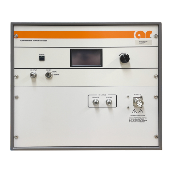
Model 250S1G6C Front Panel
30
Model 250S1G6C Rear Panel
30
Interface Identification
31
Local Controls
31
Inputs and Outputs
32
RF Input
32
RF Output
32
Rear Panel 7-16 DIN Connector
32
Align Connectors for Interface
34
Placement of Wrenches on Connector
35
IEEE-488, USB, and RS-232 Interfaces
36
Safety Interlock Connector
36
Amplifier Operation
36
Local Operation
36
Local User Interface
37
Menu Map
37
Inhibit Screen
37
Main Menu Screen
38
Select Screen
39
Mode Screen
39
User Screen
40
2.6.7 Power Indicator Frequency Screen
40
VSWR Limit Screen
41
I/O Screen
41
GPIB Address Screen
42
RS-232/Fiber-Optic Serial Baud Rate Screen
42
Key Beep Screen
43
Remote Screen
43
Fault Screen
44
ALC Lockout Feature
44
Control States
45
Power OFF, RF off
46
Power ON, RF off
46
Power ON, RF on
46
Control Lines
47
Switch Breakout Board (A14A3)
47
Fault Definition
49
No-Fault Control Actions
50
2.10 Remote Control Interfaces
51
GPIB (IEEE-488) Communications
51
RS-232 Communications
51
Fiber-Optic Serial Communications
52
USB Communications
52
Ethernet Communications
53
2.11 Remote Commands
53
Power on / off
54
RF On/Off
54
RF Gain Adjust
54
RF Gain Query
54
Power Indicator Frequency
55
VSWR Limit Selection
55
ALC Mode
56
ALC Detector Gain Adjust
56
ALC Threshold Level Adjust
56
ALC Response Setting Adjust
57
Identity Query
57
IO Board Firmware Revision Query
57
Machine State Query
58
Amplifier State Query
59
Forward Power Query
60
Reverse Power Query
61
Operating Hours (RF ON) Query
61
Operating Hours (Power ON) Query
61
Faults Query
61
Reset Faults
62
Read Fault Log
62
Read Fault Log Count
62
Clear Fault Log
63
Remote Operating Timeout (ROPTO)
63
ALC Board Firmware Query
63
SBB (Piggyback) Firmware Query
64
SBB (Optical) Firmware Query
64
System Serial Number Query
64
Default Values
65
Restore Factory Defaults
65
Theory of Operation
67
Introduction
67
RF Amplifier Operation
67
A1 Pre-Amp
67
A2 Driver Amp
67
A3, A5-A8 Quad Amp, High Power
68
A4 Four-Way Splitter
68
A9 Four-Way Combiner
68
Power Supplies (PS1, PS2, PS3)
68
Control System
69
A16 ALC Board (Schematic 10023927)
69
A14 Display Assembly, 4.3", LCD (Schematics 10029679, 10030013)
69
Maintenance
71
General Maintenance Information
71
Disassembly Procedure
71
Troubleshooting
72
General - Reading Faults
73
The Unit Cannot be Operated Remotely
73
Thermal Fault (Diagram no 10050506)
73
Interlock Fault (Diagram No. 10050506)
73
Power Supply Faults (Schematic 10050406)
74
Amplifier Faults (Schematics 10050484)
74
ALC Fault
75
Low or no Power Output (DC Tests) (Diagram 10050484)
75
Low or no Power Output (RF Test) (Diagram 10049979)
76
Typical Response @ -20 Dbm Input
76
Typical Response @ 0 Dbm Input
77
Typical Pre-Amp Response
77
Typical A2 Quad Amp Driver Response
78
Typical A1 Pre-Amp and A2 Quad Amp Driver Response
78
Typical A3 Quad Amp Gain Response
79
Removal and Re-Installation of the Dual Directional Coupler
82
Dual Directional Coupler Removal Procedure (Front Output)
82
Dual Directional Coupler Re-Installation Procedure (Front Output)
86
Dual Directional Coupler Removal Procedure (Rear Output)
88
Dual Directional Coupler Re-Installation Procedure (Rear Output)
92
Advertisement
Advertisement
Related Products
AR 250S1G2z5B
AR 250S1G6
AR 250U1000
AR 250T8G18 Series
AR 250T6G18 Series
AR 2500A225B
AR 2500L
AR 2500A225C
AR 25U1000
AR 25A250B
AR Categories
Amplifier
Measuring Instruments
Antenna
Speakers
Pressure Washer
More AR Manuals
Login
Sign In
OR
Sign in with Facebook
Sign in with Google
Upload manual
Upload from disk
Upload from URL