Sign In
Upload
Manuals
Brands
Anritsu Manuals
Measuring Instruments
MX882012C-016
Anritsu MX882012C-016 Manuals
Manuals and User Guides for Anritsu MX882012C-016. We have
1
Anritsu MX882012C-016 manual available for free PDF download: Manual
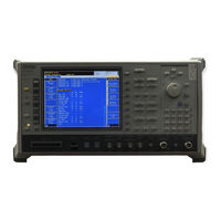
Anritsu MX882012C-016 Manual (268 pages)
LTE Measurement Radio Communication Analyzer
Brand:
Anritsu
| Category:
Measuring Instruments
| Size: 7 MB
Table of Contents
Table of Contents
2
1 LTE Measurement Software
6
Specifications
6
Mt8820C
6
Mt8821C
13
3Gpp Measurement Specification (3Gpp Ts 36.521-1 V12.5.0(2015-03)) Table
22
Operation Bands
31
Supported Ca Combination
33
Mt8820C
33
Mt8821C
35
2 The Basic Operations
38
Lte Non Ca
38
Connection Diagram
38
Initial Condition Setting
39
Location Registration
39
Test Mode Connection and Disconnection
39
Broadcast Information Update
40
2Dl Ca Without Ul Ca/2Dl Ca with Ul Ca
41
Connection Diagram
41
Synchronizing Frame Timing between 2 Cells
47
Initial Condition Setting
48
Inter-Frequency Handover
52
Location Registration
52
Test Mode Connection and Disconnection
52
Bandwidth Handover
53
Changing DL/UL RB Allocation and MCS Index of each Ccs
54
3Dl Ca
56
Connection Diagram
56
Synchronizing Frame Timing Among 3 Cells
60
Initial Condition Setting
62
Location Registration
64
Test Mode Connection and Disconnection
64
Inter-Frequency Handover
65
Bandwidth Handover
66
Changing DL/UL RB Allocation and MCS Index of each Ccs
67
4Dl Ca
68
Connection Diagram
68
Initial Condition Setting
71
Location Registration
72
Test Mode Connection and Disconnection
72
Inter-Frequency Handover
73
Bandwidth Handover
74
Changing DL/UL RB Allocation and MCS Index of each Ccs
75
3 TRX Measurements (Fundamental Measurements)
76
Tx Measurements
76
UE Maximum Output Power (6.2.2)
76
UE Maximum Output Power for HPUE (6.2.2_1)
77
Maximum Power Reduction (MPR) (6.2.3)
78
Maximum Power Reduction (MPR) for HPUE (6.2.3_1)
79
Maximum Power Reduction (MPR) for Multi-Cluster PUSCH (6.2.3_2)
80
Configured UE Transmitted Output Power (6.2.5)
81
Configured UE Transmitted Output Power for HPUE (6.2.5_1)
82
Minimum Output Power (6.3.2)
82
General ON/OFF Time Mask (6.3.4.1)
83
PRACH Time Mask (6.3.4.2.1)
84
SRS Time Mask (6.3.4.2.2)
85
Power Control Absolute Power Tolerance (6.3.5.1)
86
Power Control Relative Power Tolerance (6.3.5.2)
87
Aggregate Power Control Tolerance (6.3.5.3)
88
Aggregate Power Control Tolerance for HPUE (6.3.5_1.3)
88
Power Control Absolute Power Tolerance for HPUE (6.3.5.1_1.1)
88
Power Control Relative Power Tolerance for HPUE (6.3.5.2_1.2)
88
Frequency Error (6.5.1)
89
Error Vector Magnitude (EVM) - PUSCH (6.5.2.1)
90
Error Vector Magnitude (EVM) - PUCCH (6.5.2.1)
91
Error Vector Magnitude (EVM) - PRACH (6.5.2.1)
92
PUSCH-EVM with Exclusion Period (6.5.2.1A)
93
Carrier Leakage (6.5.2.2)
94
In-Band Emissions for Non Allocated RB - PUSCH (6.5.2.3)
94
In-Band Emissions for Non Allocated RB - PUCCH (6.5.2.3)
96
EVM Equalizer Spectrum Flatness (6.5.2.4)
98
Occupied Bandwidth (6.6.1)
100
Spectrum Emission Mask (6.6.2.1)
101
Spectrum Emission Mask for Multi-Cluster PUSCH (6.6.2.1_1)
103
Adjacent Channel Leakage Power Ratio (6.6.2.3)
104
Adjacent Channel Leakage Power Ratio for HPUE (6.6.2.3_1)
106
Adjacent Channel Leakage Power Ratio for Multi-Cluster PUSCH (6.6.2.3_2)
106
Additional Maximum Power Reduction (A-MPR) (6.2.4)
107
Additional Maximum Power Reduction (A-MPR) for HPUE (6.2.4_1)
108
Additional Spectrum Emission Mask (6.6.2.2)
109
Rx Measurements
110
Reference Sensitivity Level (7.3)
110
Maximum Input Level (7.4)
111
Spurious Emissions (7.9)
112
Tx Measurements for Ca
113
TX Measurements for Inter-Band CA
113
TX Measurements for Intra-Band Contiguous CA
129
Rx Measurements for Ca
148
Reference Sensitivity Level for CA (Intra-Band Contiguous DL CA and UL CA) (7.3A.1)
148
Reference Sensitivity Level for CA (Intra-Band Contiguous DL CA Without UL CA) (7.3A.2)
148
(7.3A.4)
149
Reference Sensitivity Level for CA (Inter-Band DL CA Without UL CA) (7.3A.3)
149
Reference Sensitivity Level for CA (Intra-Band Non-Contiguous DL CA Without UL CA)
149
Maximum Input Level for CA (Intra-Band Contiguous DL CA and UL CA) (7.4A.1)
150
Maximum Input Level for CA (Inter-Band DL CA Without UL CA) (7.4A.3)
151
Maximum Input Level for CA (Intra-Band Contiguous DL CA Without UL CA) (7.4A.2)
151
Maximum Input Level for CA (Intra-Band Non-Contiguous DL CA Without UL CA) (7.4A.4)
151
Rx Measurements for 3Dl Ca
152
Throughput Measurement Example
152
Rx Measurements for 4Dl Ca
154
Throughput Measurement Example
154
RX Measurements for MT8821C UL CA 2Ccs
155
Restrictions
155
Required Options
155
Connection Diagram
156
UL Throughput Measurement
156
Test Parameters Supporting 3Gpp Test Items
159
Remote Commands List Limiting Pass/Fail Judgment
164
4 Band 13 Supplementary Rf Conformance Measurement
170
Pucch Over-Provisioning Functional Test (2.7)
170
Spurious Emissions with Tx Gating (2.9)
170
5 IP Data Transfer Test
172
IP Data Transfer Test for Non CA (Single Cell)
172
Connection Diagram
172
Application Server Connection and Setting
175
Client PC Connection and Setting
183
Initial Condition Setting
184
Location Registration and Packet Connection
189
TCP/UDP Throughput
194
IP Data Transfer Test with Connected DRX
196
RRC State Transition Test
197
Ip Data Transfer Test for 2Dl Ca
198
Connection Diagram
200
Application Server Connection and Setting
203
Client PC Connection and Setting
206
Synchronizing Frame Timing between 2 Cells
206
Initial Condition Settings
207
Location Registration and Packet Connection
215
TCP/UDP Throughput
216
Ip Data Transfer Test for 3/4Dl Ca
217
Connection Diagram
218
Application Server Connection and Setting
220
Client PC Connection and Setting
220
Initial Condition Settings
221
Location Registration and Packet Connection
228
TCP/UDP Throughput
229
CS Fallback to W-Cdma/Redirection to W-CDMA
230
Ort Cs Fallback /Redirection
230
CS Fallback to TD-Scdma/Redirection to TD-SCDMA
231
CS Fallback to Gsm/Redirection to GSM
232
CS Fallback to Cdma2000/Redirection to CDMA2000
233
Redirection to 1Xev-DO
234
Cell Reselection
235
Cell Selection Criterion
235
Measurement Rules for Cell Reselection
237
Inter-RAT Cell Reselection Criteria
238
Intra-Frequency and Equal Inter-Frequency Cell Reselection Criteria
238
Cell Reselectionprocedure
239
Initial Condition Setting
242
Measurement Report
242
Measurement Report Procedure
242
6 Rrm
230
7 LTE Volte Echoback Test (MT8821C Only)
246
LTE Volte Echoback Test
246
Connection Diagram
246
Application Server Connection and Setting
247
Initial Condition Setting
253
Registration and IMS Registration
255
Echoback Test
255
Downlink Fixed Data Test
256
Downlink SID Data Test
256
Annex A: ARB Waveform List
258
A.1. ARB Waveform Installer Version: Q007
258
A.2. ARB Waveform Installer Version: Q008
258
Annex B: Informative
260
B.1. Ue Dl-Sch Rx
260
B.1.1. UE Category
260
B.1.2. Code Rate
260
B.1.3. Error Free Setting
263
B.2. Carrier Leakage Frequency
264
B.2.1. Transmitter lo Configuration
264
B.2.2. TX Measurement Parameter
265
B.3. about Optimization of the TCP Throughput Using Iperf
266
B.3.1. Setting of TCP Window Size
266
B.4. Setting for DL 256QAM Maximum Throghput Rate
267
Advertisement
Advertisement
Related Products
Anritsu MX882012C-006
Anritsu MX882012C-011
Anritsu MX882012C-017
Anritsu MX882012C-018
Anritsu MX882012C-021
Anritsu MX882012C-022
Anritsu MX882012C-026
Anritsu MX882012C-031
Anritsu MX882013C-011
Anritsu MX882013C-022
Anritsu Categories
Measuring Instruments
Test Equipment
Portable Generator
Control Unit
Thermometer
More Anritsu Manuals
Login
Sign In
OR
Sign in with Facebook
Sign in with Google
Upload manual
Upload from disk
Upload from URL