Sign In
Upload
Manuals
Brands
Anritsu Manuals
Measuring Instruments
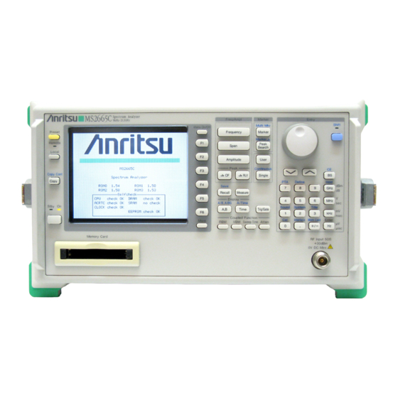
MS2665C
Anritsu MS2665C Manuals
Manuals and User Guides for Anritsu MS2665C. We have
2
Anritsu MS2665C manuals available for free PDF download: Operation Manual, Service Manual
Anritsu MS2665C Operation Manual (279 pages)
Spectrum Analyzer
Brand:
Anritsu
| Category:
Measuring Instruments
| Size: 4 MB
Table of Contents
Table of Contents
19
For Safety
4
About this Manual
18
Table of Contents
19
General
23
Product Outline
24
Composition of Operation Manual
25
Equipment Configuration
26
Standard Configuration
26
Options
27
Optional Accessories and Peripherals
28
Specifications
30
Section 2 Preparations before Use
44
Fan Clearance
46
Iinstallation Site and Environmental Conditions
46
Locations to be Avoided
46
Preparations before Use
46
Power-On
47
Safety Measures
47
Connector of RF Input
48
Input Level to RF Input
48
Installation
49
Rack Mounting
49
Preparations before Power-On
50
Connecting the Power Cord
51
Replacing Fuse
52
Precaution for Handling Memory Card
54
Panel Description
57
Table of Front and Rear Panel Features
58
Soft-Key Menu
66
Soft-Key Menu List
67
Menu Tree
71
Section 5 Basic Operation Procedure
122
Basic Operation Procedure
123
Check of the Zone Marker Function
124
Enlarge and Display the Signal
124
Execute Automatic Calibration
124
Marker Operation
124
Set the Signal to the Center of the Screen
124
Signal Display
124
The "Marker → CF" Function Check
124
Turn the Power on
124
Execute Automatic Calibration
125
Set the Signal to the Center of the Screen
125
Enlarge and Display the Signal
126
Marker Operation
127
Section 6 Performance Tests
132
Requirement for Performance Tests
134
Instruments Required for Performance Test
136
Performance Test
137
Reference Oscillator Frequency Stability
138
Frequency Readout Accuracy
140
Frequency Span Readout Accuracy
145
Resolution Bandwidth (RBW) and Selectivity
149
Sideband Phase Noise
155
Frequency Measurement Accuracy
158
Amplitude Display Linearity
160
Frequency Response
164
Reference Level Accuracy
170
Average Noise Level
173
Second Harmonic Distortion
178
Resolution Bandwidth (RBW) Switching Uncertainty
181
Input Attenuator (RF ATT) Switching Uncertainty
184
Sweep Time and Time Span Accuracy
187
Service
191
Section 7 Storage and Transportation
192
Cleaning Cabinet
194
Precautions before Storage
195
Recommended Storage Precautions
195
Storage Precautions
195
Repacking
196
Repacking and Transportation
196
Transportation
196
Advertisement
Anritsu MS2665C Service Manual (178 pages)
Brand:
Anritsu
| Category:
Measuring Instruments
| Size: 7 MB
Table of Contents
Section 1
5
Table of Contents
5
Section 1 General
7
Section 2
9
Overall Circuit Description
10
Section 2 MS2665C
14
Introduction
17
Required Equipment
17
Service Kit
17
Troubleshooting
17
Circuit Reference
18
Detecting Faulty Module
21
Disassembling Cabinet
23
Replacement of Faulty Module
23
Adjustment after Module Replacement
24
Reference Crystal Oscillator (Option 01) Adjustment
24
Sweep Adjustment
26
IF1 (ATT), IF2 (AMP) Adjustment
32
Checking Items after Assembling Cabinet
34
Frequency Response Compensation
35
Disassembling/Assembling Cabinet
39
Mechanical Configuration
39
Removing/Assembling Units and PC Boards
43
Front Unit Disassembly/Assembly
47
A09 OPTION BASE Disassembly/Assembly
51
Section 3 Ms2667C
57
Overall Circuit Description
58
Section 3 MS2667C
62
Introduction
65
Required Equipment
65
Service Kit
65
Troubleshooting
65
Circuit Reference
66
Detecting Faulty Module
71
Adjustment after Module Replacement
72
Disassembling Cabinet
72
Reference Crystal Oscillator Adjustment
72
Replacement of Faulty Module
72
Sweep Adjustment
72
IF Gain-1 (ATT), if Gain-2 (AMP) of Internal Mixer Band Adjustment
82
IF Gain-1 (ATT), if Gain-2 (AMP) of External Mixer Band Adjustment
86
Assembling Cabinet
88
Checking Items after Assembling Cabinet
88
Frequency Response Compensation
88
Disassembling/Assembling Cabinet
89
Mechanical Configuration
89
Removing/Assembling Units and PC Boards
93
Disassembling/Assembling Components Around RF Input
97
Disassembling/Assembling Units and Components on Lower Surface
101
Front Unit Disassembly/Assembly
107
OPTION BASE Disassembly/Assembly
111
Removing/Assembling A0501 HI-SPEED AD from SCAN/AD
115
Connecting the Cable to Diplexing Bandswitch and F2626 (YTF)
116
Section 4 Ms2668C
117
Overall Circuit Description
118
Section 4 MS2668C
122
Overall Circuit Description
123
Introduction
125
Required Equipment
125
Service Kit
125
Troubleshooting
125
Circuit Reference
126
Detecting Faulty Module
131
Adjustment after Module Replacement
132
Disassembling Cabinet
132
Reference Crystal Oscillator Adjustment
132
Replacement of Faulty Module
132
Sweep Adjustment
132
IF Gain-1 (ATT), if Gain-2 (AMP) of Internal
138
Mixer Band Adjustment
138
Mixer Band Adjustment
141
Assembling Cabinet
142
Checking Items after Assembling Cabinet
142
Frequency Response Compensation
142
Disassembling/Assembling Cabinet
143
Disassembling/Assembling Components Around RF Input
143
Disassembling/Assembling Units and Components on Lower Surface
143
Mechanical Configuration
143
Removing/Assembling Units and PC Boards
143
A09 OPTION BASE Disassembly/Assembly
149
Connecting the Cable to Diplexing Bandswitch and F2626 (YTF)
149
Front Unit Disassembly/Assembly
149
Removing/Assembling A0501 HI-SPEED AD from A05 SCAN/AD
149
Section 5 Firmware Installation
151
Section 6 Performance Test System
153
Required Instruments
154
Required Software
154
Setup
155
Test Group 1
155
Test Items
155
Test Group 2
156
Setup
157
Test Group 2
157
Test Group 3
158
Test Items
158
Setup
159
Section 7 Options
161
Introduction
162
Option Structure Summery
162
Retrofit
162
Cabinet Disassembly/Assembly
163
Option 04 Hi-Speed Time Domain Sweep
163
Parts, PC Board Installation
163
Parts/Pcbs Fitting for each Option
163
Option 07 AM/FM Demodulator (Voice Monitor)
165
Option10 Centronics Interface
166
Software Setting
167
Option 04 Hi-Speed Time Domain Sweep
171
Performance Test
171
Option 06 Trigger/Gate Circuit
172
EXT TRIG Check
173
GATE Check
174
VIDEO Trig Check
174
Line TRIG Check
175
Wide if Video Trig Check
175
Option 07 AM/FM Demodulator (Voice Monitor)
176
Measure of am Voice Monitor Voltage
177
Measure of FM Voice Monitor Voltage
177
Advertisement
Related Products
Anritsu MS2661B
Anritsu MS2667C
Anritsu MS2668C
Anritsu MS2661N
Anritsu MS2687B
Anritsu ms2602a
Anritsu MS2690
Anritsu MS2651B
Anritsu MS2681A
Anritsu MS2683A
Anritsu Categories
Measuring Instruments
Test Equipment
Portable Generator
Control Unit
Thermometer
More Anritsu Manuals
Login
Sign In
OR
Sign in with Facebook
Sign in with Google
Upload manual
Upload from disk
Upload from URL