Sign In
Upload
Manuals
Brands
Anritsu Manuals
Measuring Instruments
ML2437A
Anritsu ML2437A Manuals
Manuals and User Guides for Anritsu ML2437A. We have
3
Anritsu ML2437A manuals available for free PDF download: Operation And Programming Manual, Operation Manual, Maintenance Manual
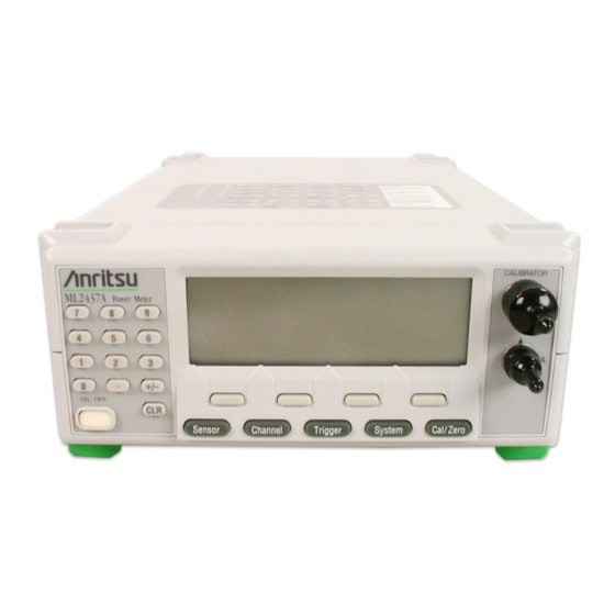
Anritsu ML2437A Operation And Programming Manual (314 pages)
Power Meter
Brand:
Anritsu
| Category:
Measuring Instruments
| Size: 2 MB
Table of Contents
Table of Contents
3
Chapter 1-General Information
21
About this Manual
21
Associated Documentation and Software
21
Identification Number
21
Available Models
21
Available Options, Accessories, and Power Sensors
21
Chapter 2-Installation
23
Initial Inspection
23
Sensor Handling
23
Power Requirements
23
AC Line Power
23
DC Power
23
Battery Power
24
Fuses
24
Grounding
24
Environmental Requirements
24
Rack Mounting
25
Battery Charging, Removal and Replacement
25
Storage and Shipment
27
Preparation for Storage
27
Environmental Requirements
27
Preparing for Shipment
27
Chapter 3-Memory And Security Considerations
29
Introduction
29
Internal Flash Memory (8 MB EEPROM)
29
RAM Memory Used by the DSP Microcomputer (640 KB)
29
RAM Memory as Non-Volatile RAM (1 MB)
29
Secure Mode
29
Clearing the Non-Volatile Static RAM
30
Anritsu Power Sensors EEPROM
30
EEPROM Contents
30
Chapter 4-Connections
31
Front Panel Connectors
31
Calibrator Connector
31
Sensor a Connector
31
Sensor B Connector (ML2438A Only)
32
Rear Panel Connectors
32
Chapter 5-Front Panel Operation
35
ML2437A/38A OM/PM PN: 10585-00001 Rev. P
35
Front Panel Controls
36
Power-On Procedure
37
Sensor Menu
39
Setup
39
Calfactor
40
Averaging
43
Offset
45
Duty Cycle
46
Rng Hold [RGH]
46
Channel Menu
47
Setup
47
Rel 1 [REL]
48
Rel 2 [REL]
48
Limits
48
Trigger Menu
50
Setup
51
System Menu
56
Setup
56
Profile
57
Power Vs. Time
58
Source Sweep
59
Control
60
Display
64
Sound
65
Print [PRINT]
66
Battery
66
Rear Panel
67
Graphics
70
Secure [SECURE]
71
Identity [*IDN, OI]
71
Cal/Zero Menu
72
Zero/Cal
72
Cal 0 Dbm [CAL]
72
Zero [ZERO]
72
Rf On/Off [Rfcal]
72
Ext V [VZERO]
72
Chapter 6-Procedures
73
Power Measurement
73
Zeroing the Sensor
73
Sensor Calibration
74
Sensor Zero/Cal
74
Performance Verification
75
Printer Connection
75
GPIB Remote Operation
75
Serial Remote Operation
76
RS232 Modem Support
77
6-10 Profile Operation Mode
82
Typical Setup
82
Scaling
83
Cursor Readout
83
Triggered Measurements
84
Control of X-Axis - Width of Profile - Sample Time
85
Advanced Triggering and Setup Options
86
Source Sweep Mode
87
Frequency Sweep Mode
87
Power Sweep Mode
87
Source Sweep Graph
88
Using an Anritsu Synthesizer
88
6-12 Power Vs. Time Mode
89
6-13 User Cal Factors
89
Example Procedure
90
Readout Mode
90
6-14 Optimizing Readings
91
DISP ON/OFF Command
92
FAST ON/OFF Command
93
Using Buffered Requests
93
Changing Measurement Modes
94
An Example Program in C
95
6-15 Operator Maintenance
96
Software Loader Instructions
96
Chapter 7-Measurement Examples
97
Example 1: Standard CW Power Measurements
97
Example 2: Measuring Modulated Carrier
104
Example 3: Optimizing Measurements at Low Power Levels
105
Example 4: Using both Channels
107
Example 5: Using Two Sensors
109
Example 6: Gain Compression Measurement
111
Example 7: Measuring Pulse Signals with a Duty Cycle
113
Example 8: Profiling Pulse Signals
115
Example 9: Displaying GSM-TDMA Bursts
119
7-10 Example 10: Power Versus Time Data Logging
123
Example 11: Frequency Measurements Using a Separate Source
127
Chapter 8-GPIB Operation
131
Data I/O Formats
131
Nr1
132
Nr2
132
Nr3
133
Nrf
133
String
133
Arbitrary ASCII
133
Arbitrary Block
133
Query Commands
134
GPIB PC Card Setup
134
GPIB Device Template
134
Using 488.1 GPIB
135
Device Clear (DCL) and Selected Device Clear (SDC)
135
Device Trigger (GET)
135
Goto Local (GTL)
135
Interface Clear (IFC)
135
Serial Poll
135
Using 488.2 GPIB
136
488.2 Command Format
136
Status Byte
136
Event Status Bit (ESB)
136
Message Available Bit (MAV)
137
Getting a Reading
138
Service Request Status (SRQ)
138
Rgh
138
Lim
138
Mav
138
Esb
138
Functional Groups
139
Bnc
139
Calibration
139
Channel
139
Data Output
139
Display
139
Gpib 488.2
139
GPIB Setup
139
GPIB Trigger
139
Profile Setup
140
Sensor
140
System
140
Trigger
140
Ml24Xxa Native Commands
141
CLS (Clear GPIB Status Bytes)
141
ESE (Event Status Byte Enable)
142
ESE? (Return Event Status Register Enable Mask)
144
ESR? Event Status Register Request
144
IDN? (Request Device Identification)
144
OPC (Operations Complete)
144
OPC? (Operations Complete Output '1')
144
RCL (Recall a Stored Setup)
145
RST (Reset Device)
145
SAV (Save Configuration)
145
SRE (Setup Service Request Enable Register)
145
SRE? (Return Service Request Enable Register)
146
STB? (Return Status Byte Register)
146
TRG (Perform the GPIB 'Group Execute Trigger' Command)
146
TST? (Self Test)
146
ADDR (Change GPIB Address)
147
AVG (Sets up Averaging for a Sensor)
148
AVGLL (Auto Low Level Averaging)
149
AVGM (Manual Averaging)
149
BAUTS (Battery Auto Turn OFF)
150
BAUTT (Battery Auto Shut off after X Minutes)
150
BUFF (GPIB Response Buffering Enabled)
150
CAL (Cal Sensor to 0 Dbm Reference)
151
CFADJ (Cal Adjust)
151
CFCAL (Cal Factor Manual Setting)
151
CFFRQ (Cal Factor Frequency Value)
152
CFSRC (Cal Factor Source)
152
CFUADD (Add an Entry Pair to a Cal Factor Table)
153
CFUCT (Clear Cal Factor Table)
153
CFUID (Cal Factor Table Identity Update)
154
CFUNITS (Cal Factor Display Units)
154
CFULD (Cal Factor Table Binary Load)
154
CFUPT (Preset Cal Factor Table)
155
CFURD (Cal Factor Table Binary Read)
155
CFUSEL (Select Cal Factor Table)
156
CFUTBL (Number of Cal Factor Tables in the Sensor)
156
CFUUSE (Number of Cal Factor Table Being Used)
156
CFUVLD (Valid Cal Factor Table Check)
156
CFVAL Current Cal Factor Value
157
CHCFG (Channel Input Configuration)
157
CHRES (Set Channel Decimal Pint Resolution)
158
CHUNIT (Set Channel Units)
158
CONT (Continue)
158
CUR (Cursor in Power Vs. Time and Source Sweep Modes)
159
CURLK (Link Cursors in All Graphic Modes)
159
CVSPF (V/Ghz Calibration Factor Stop Frequency)
160
CVSPV (V/Ghz Calibration Factor Stop Voltage)
160
CVSTF (V/Ghz Calibration Factor Start Frequency)
160
CVSTV (V/Ghz Calibration Factor Start Voltage)
161
DBLGHT (Battery LCD Back Light Mode)
161
DBLTIM (Auto Backlight off Timer Setting)
161
DCONT (Set Display Contrast)
162
DCONTD (Set Display Contrast down by One)
162
DCONTU (Set Display Contrast up by One)
162
DISP (Display on or OFF)
162
DTRGD (Display Trigger Delay)
163
DUTY (Duty Cycle)
164
DUTYS (Duty Cycle State)
164
EMUL (GPIB Emulation Mode)
165
ENTERR (Entry Error Beep)
165
ERRLST (Returns the DDE Error List)
166
FAST (Operate in Non-488.2 Compliant Mode)
167
FHOLD (Fail Indicator Hold)
168
FRST (Factory Reset)
169
GMNMX (Return the Minimum and Maximum Values)
169
GPRST (Reset Min/Max Graph)
170
GRAUTO (Auto Scaling)
170
GRAVG (Average between Profile Cursors)
170
GRCP (Connect Points on Profile)
170
GRDATA (Display Graph Cursor Data)
171
GRDDT (Power Vs. Time Data Display Time)
171
GRDRQ (Return Graph Data Readout)
172
GRFS (Profile Reference Line State)
172
GRMD (Profile, Power Vs. Time and Source Sweep Selection)
172
GRPIX (Profile Type)
173
GRPRD (Profile Data Collection Period)
173
GRPTP (Graph Pretrigger Percentage)
173
GRSWP (Graph Averaging Number for Profile or Source Sweep)
174
GRSWR (Reset Graph Averaging for Profile or Source Sweep)
174
GRSWS (Graph Average State for Profile or Source Sweep)
174
GRTMM (Profile Min/Max Tracking Mode)
175
GRYB (Set Graph Y-Axis Bottom Scale)
175
GRYT (Set Graph Y-Axis Top Scale)
175
GT0 (Set to Ignore the Group Execute Trigger (GET) Command)
176
GT1 (Set 'GET' Command to TR1 Type (Immediate) Trigger)
176
GT2 (Set 'GET' Command to TR2 Type (Settling Delay) Trigger)
176
GTARM (Set Profile Trigger Arming)
176
GTDLY (Set Profile Trigger Sample Delay)
177
GTGW (Set Profile Trigger Gate Width)
177
GTLVL (Set Profile Trigger Level)
177
GTSRC (Set Profile Trigger Source)
178
GTTYP (Set Profile Trigger Type)
178
GTXTTL (Set Profile External Trigger Edge)
179
HLIM (Set High Limits)
180
HLIMS (Turn On/Off High Limits)
180
IBBLP (Blanking Active TTL Level)
180
KEYCK (Turn Key Click Sound on or Off)
181
LINK (Trigger Linking)
181
LLIMS (Turn On/Off Low Limits)
182
MMRST (Min Max Tracking Reset)
183
MNGDB (Output Min Graph Binary Data)
183
MNGD (Output Min Graph Data)
183
MNMXS (Track Min and Max Values)
184
MODDEL (Modem Redial Delay Time)
184
MODINIT (Initialize Modem)
184
MODLIM (Autodial Enable for Limits Failure)
184
MODPH (Autodial Phone Number)
185
MODPWR (Autodial Enable for Power On)
185
MODRED (Redial Count)
185
MODRNG (Autodial Enable for Range Error)
186
MXGDB (Output Max Graph Binary Data)
186
MXGD (Output Max Graph Data)
186
O (Return Display Channel Reading)
187
OBACM (AC Mod Output Polarity Configuration)
187
OBCH (BNC Output Port Channel Configuration)
187
OBDSP (BNC Analog Output Display Stop Value)
188
OBDST (BNC Analog out Display Start Value)
188
OBMD (BNC Output Mode Select)
189
OBPL (BNC Pass/Fail Pass Level)
189
OBVSP (BNC Analog Output Stop Voltage Scale)
190
OBVST (BNC Analog Output Start Voltage Scale)
190
OBZL (BNC RF Blanking Output Level When Zeroing)
190
OFFCLR (Clear an Offset Table)
190
OFFFIX Offset Fixed Value
191
OFFTBL (Specify the Table Used to Apply Offsets to the Sensor)
191
OFFTBU (Updates an Offset Table)
192
OFFTYP (Offset Type to Use)
193
OFFVAL (Sensor Offset Value)
193
OGBD (Output Graph Binary Data)
193
OGD (Output Graph Data)
194
OGSD (Output Valid Samples Array (Power Vs. Time Mode Only))
194
OI (Output Device Identification)
194
ON (Output Number of Channel Readings)
195
OPMD (Ml243Xa Operation Mode)
195
PRINT (Send Details to the Connected Printer.)
196
RCD (Range Calibrator Data Request)
196
REL (Relative Control)
197
RFCAL (Turn RF Reference Calibrator on or OFF)
197
RGH (Range Hold Sensor)
197
RSBAUD (RS232 Baud Rate)
198
RSMODE (RS232 Operating Mode)
198
SECURE (Secure System State)
198
SENMM (Sensor Measurement Mode)
199
SENMO (Universal Sensor Operation Mode)
199
SENSTL (Set Sensor Settle Percentage)
200
SENTYP (Return Sensor Information)
200
SRCMOD (Source Sweep Mode)
200
SRCSPFRQ (Source Sweep Stop Frequency)
200
SRCSPPWR (Source Sweep Stop Power)
201
SRCSTAT (Source Sweep Mode Status Request)
201
SRCSTFRQ (Source Sweep Start Frequency)
201
SRCSTPWR (Source Sweep Start Power)
201
START (Initial Startup Self Test Command)
202
STATUS (Status Message)
203
STERR (Returns Results of POST or *TST?)
205
SYSLD (Load Saved Setup Store over the GPIB)
205
SYSLNM (Saved Set Naming)
206
SYSRD (Output the Saved Setup over the GPIB)
206
TEXT (User Text Command)
207
TEXTS (User Text Display Command)
207
TR0 (Trigger Hold Mode)
207
TR1 (Trigger Immediate)
208
TR2 (Trigger with a Settling Delay)
208
TR3 Trigger Free Run
209
TRGARM (Trigger Arming)
209
TRGDLY (Trigger Sample Delay)
210
TRGGW (Set Trigger Gate Width)
210
TRGLVL (Set Trigger Level)
211
TRGMODE (Change Trigger Mode)
211
TRGSRC (Set Trigger Source)
212
TRGTYP (Set Trigger Type)
212
TRGXTTL (Set External Trigger Edge Type)
213
VZERO (Zero the BNC Input Connector)
213
ZERO (Zero the Selected Sensor)
213
GPIB Emulation Modes
214
Zeroing a Sensor
214
Sensor Ranges
214
Output Format
214
8-10 ML4803A Emulation Commands
215
Srqs
215
Status Byte
215
Output Requests
216
Unsupported Commands
216
AVE (Sensor Averaging Setting)
217
CAL (Set the User Cal Factor Value)
217
CCA (Clear the Calfactor Value to Zero)
217
CDJ (Perform a CAL 0 Dbm)
217
COF (Clear the Offset Value to Zero)
217
COS (Turn on the 50 Mhz, 0 Dbm RF Calibrator Output)
217
CRF (Clear the Reference Value to Zero)
217
CST (Turn off the 50 Mhz, 0 Dbm RF Calibrator Output)
217
DBM (Sets the Display Channel Units to Dbm)
218
DBR (Sets Display Channel Units to Db's and Takes the Relative Value)
218
EMUL (GPIB Emulation Mod)
218
MCA (Set the Cal Factor Value at the Specified Memory Location in Dbm)8-88
218
MCC (Clears the Cal Factor Value at the Specified Memory Location)
219
MCO (Clears the Offset Value at the Specified Memory Location)
219
MCQ (Clears the Frequency Value at the Specified Memory Location)
219
MCR (Clears the Reference Value at the Specified Memory Location)
219
MCT (Clears All the Entries at the Specified Memory Location)
219
MDI (Disable Memory Store Setting and Use)
219
MEN (Enable Setting of the Memory Stores)
219
MFG (Set the Frequency Value at the Specified Location in Ghz)
220
MFM (Set the Frequency Value at the Specified Location in Mhz)
220
MOF (Set the Offset Value at the Specified Location in Dbm)
220
MRF (Set the Reference Value at the Specified Location in Dbm)
220
ODT (Output the Current Calibration Factor, Offset, and Reference Level)8-91
221
OFF (Set Sensor Offset Value)
221
OI? (Request Identity)
221
OMR (Output a Memory Store Set of Data)
222
OPW (Request for Channel Reading)
222
REF (Set the Reference Value)
225
RNG (Sensor Measurement Range Hold)
225
SRQ (Turns on or off the SRQ on Output Data Ready)
225
STA (Restart Averaging Reading)
225
WAT (Sets the Display Channel Units to Watts)
225
ZAJ (Zero the Sensor)
226
HP436A Emulation Commands
227
(Disable Cal Factor)
227
(Enable Cal Factor)
227
1, 2, 3, 4, & 5 (Set Sensor Operating Range)
227
Auto Range)
227
A (Wat)
227
B (Db (Rel)
228
C (Db (Ref)
228
D (Db)
228
EMUL (Select Emulation Mod)
228
H (Hold Mod)
229
I (Trigger Without Settling)
229
R (Free Run Mod)
229
T (Trigger with Settling)
229
Free Run Mode with Settling)
229
Z (Zero Sensor)
230
Output Format
230
8-12 HP437B Emulation Commands
232
CLS (Clear GPIB Status Byte)
233
ESE (Set the Event Status Register Enable Mask)
233
ESE? (Return Event Status Register Enable Mask)
235
ESR? (Event Status Register Request)
235
RST (Reset Device)
235
SRE (Setup Service Request Enable Register)
235
SRE? (Return Service Request Enable Register)
235
STB? (Return Status Byte Register)
236
TST? (Self Test)
236
Set SRE Mask)
236
CL (Cal Adjust)
237
CS (Clear All Status Byte)
237
CT (Clear the Cal Factor Table)
237
DA (Display All)
237
DC (Duty Cycle State)
238
DD (Display Disable)
238
DE (Display Enable)
238
DF (Display Disable)
238
DR (Set GPIB Address)
238
DY (Duty Cycle)
239
EMUL (GPIB Emulation Mode)
239
EN (Enter Command)
240
EX (Exit Cal Factor Table Mode)
240
FA (Auto Average)
240
FH (Average Hold)
241
FM (Set Average Value)
241
FR (Frequency of the Input Signal)
241
GT (Set Group Trigger)
242
ID (Return Identification String)
242
IDN? (HP437B Identity Request)
242
KB (Calibration Factor)
243
LG (Set Log Units)
243
LH (Set High Limit)
243
LL (Set Low Limit)
243
LM (Limits Check State)
244
LN (Set Linear Units)
244
OC (Set Calibrator State)
244
OD (Output the Display)
244
OF (Offset State)
245
OI (Return Identification String)
245
OS (Set Offset Value)
245
PR (Preset the Unit)
245
RA (Auto Range)
245
RC (Recall Setup)
246
RE (Set Decimal Point Resolution)
246
RF (Set the Reference Cal Factor Value for a Table)
246
RH (Range Hold)
246
RL (Relative Mode)
247
RM (Range Hold Set)
247
RV (Service Request Mask Value)
247
SE (Select Cal Factor Table)
247
SM (Status Message)
248
ST (Store Setup)
249
SV (Save Cal Factor Table)
249
TR0 (Trigger Hold Mode)
249
TR1 (Trigger Immediate)
250
TR2 (Trigger with a Settling Delay)
250
TR3 (Trigger Free Run)
250
ZE (Zero Sensors)
250
ID (HP Identity Request)
252
BP (Set Single Sensor B Display)
253
DE (Display Enable)
254
FH (Average Hold)
255
KB (Calibration Factor)
256
LN (Set Linear Units)
257
PR (Preset the Unit)
258
RL (Relative Mode)
259
SM (Status Message)
260
TR0 (Trigger Hold Mode)
261
Programming Examples
262
Get Graph Data
263
Status Register Control
264
Binary Output Message Decoding
266
A-1 Getting Support
271
B-1 System Configuration
273
B-2 System Defaults
275
B-3 System Error Messages
282
B-4 Calibration and Zero Error Codes
284
C-1 ML24XXA Quick Reference
285
Appendix A-Technical Support
286
Appendix B-Specifications
286
Appendix C-Gpib Quick Reference
286
Data Output Functional Group Commands
286
Display Functional Group Commands
287
GPIB Trigger Functional Group Commands
288
Sensor Functional Group Commands
289
System Functional Group Commands
290
Trigger Functional Group Commands
291
ML24XXA Native Mode Query Commands
292
C-2 ML4803A Quick Reference
296
C-3 HP436A Quick Reference
298
C-4 HP437B Quick Reference
299
C-5 HP438A Quick Reference
300
C-6 HP-IB Support
302
HP438A Commands
305
D-1 Pin Depth Mating Connectors
307
D-2 Torquing Connectors
308
D-4 Cleaning Connectors
309
Advertisement
Anritsu ML2437A Operation Manual (271 pages)
POWER METER
Brand:
Anritsu
| Category:
Laboratory Equipment
| Size: 1 MB
Table of Contents
Limitation of Warranty
2
Trademark Acknowledgments
2
Safety Symbols
3
Table of Contents
6
Chapter 1 - General Information
9
Scope of this Manual
9
Introduction
9
Related Manuals
9
Identification Number
10
Power Meter Models, Options, and Accessories
10
Sensors
11
Chapter 2 - Installation
13
Introduction
13
Initial Inspection
13
Sensor Handling
13
Power Requirements
14
Environmental Requirements
15
Rack Mounting
16
Battery Charging, Removal and Replacement
21
Battery Cover
21
Storage and Shipment
23
Chapter 3 - Connections
25
Introduction
25
Front Panel Connectors
25
Rear Panel Connectors
26
Front Panel Controls
30
Power-On Procedure
31
Operation
31
Test Sequence
31
Sensor Menu4-5
33
Channel Menu
41
Trigger Menu
44
Trigger Point
48
System Menu
49
Cal/Zero Menu
63
Chapter 5 - Procedures
64
Introduction
64
Power Measurement
64
Zeroing the Sensor
64
Sensor Calibration
65
Sensor Zero/Cal
66
Performance Verification
66
Printer Connection
67
GPIB Remote Operation
67
Serial Remote Operation
68
RS232 Modem Support
70
Profile Operation Mode
74
System|Setup|Mode
74
Typical Setup
74
Cursor Readout
75
Source Sweep Mode
80
Power Vs. Time Mode
81
User Cal Factors
82
Optimizing Readings
84
Operator Maintenance
87
Chapter 6 - GPIB Operation
88
Introduction
88
Typographic Conventions
88
Data I/O Formats
89
Query Commands
91
GPIB PC Card Setup
92
Using 488.1 GPIB
93
Using 488.2 GPIB
94
Service Request Status (SRQ)
96
Functional Groups
97
ML24XXA Native Commands
100
Set|Reset
102
GPIB Emulation Modes
170
ML4803A Emulation Commands
171
HP 436A Emulation Commands
185
HP 437B Emulation Commands
188
HP 438A Emulation Commands
204
Programming Examples
215
Appendix A Specifications
223
Introduction
223
System Specifications
224
System Configuration
225
System Defaults
228
System Error Messages
233
Appendix Bgpib Quick Reference
235
Introduction
235
ML24XXA Quick Reference
240
ML4803A Quick Reference
243
HP 436A Quick Reference
244
HP 437B Quick Reference
245
HP 438A Quick Reference
248
HP-IB Support
250
Appendix C Menu Maps
254
Introduction
254
Sensor Menu
254
Channel Menu
259
Trigger Menu
261
System Menu
262
Gpib Address
265
Cal/Zero Menu
268
Anritsu ML2437A Maintenance Manual (78 pages)
POWER METER
Brand:
Anritsu
| Category:
Measuring Instruments
| Size: 1 MB
Table of Contents
Limitation of Warranty
2
Trademark Acknowledgments
2
Safety Symbols
3
For Safety
4
Table of Contents
5
Chapter 1 General Information
7
Scope of this Manual
7
Introduction
7
Related Manuals
7
Identification Number
8
Models, Options, and Accessories
8
Service Policy
9
Spare Parts Listing
9
Component Handling
10
Chapter 2 Performance Verification
11
Introduction
11
Test Conditions
11
Input Range
12
Range Data Interpretation
15
Range Calibrator Diagnostics
16
Calibrator Frequency
17
Calibrator Power Level
23
Chapter 3 Calibration Procedures
33
Introduction
33
Required Test Equipment
33
Test Conditions
34
Pre-Test Setup
35
DC Reference
37
Calibrator Frequency
38
Calibrator Power Level
39
Chapter 4 Theory of Operation
41
Introduction
41
Product Overview
41
General Operation
42
Human Interface
42
Gpib Operation
43
Printer
43
Case Construction
43
Internal Construction
43
Front Panel
44
Front Panel Connectors
44
Rear Panel Connectors
45
Power Supply Operation
46
Battery Operation
46
Chapter 5 Firmware Updates
49
Introduction
49
Code Loader Program
50
Bootload Mode
51
Serial Interface Cable
52
Chapter 6 Troubleshooting
53
Introduction
53
Front Panel
54
Rear Panel
56
Battery
57
General Faults
58
Chapter 7 Removal and Replacement Procedures
59
Introduction
59
Front Panel
60
Removal and Replacement
60
Power Supply
62
Main Pcb
63
Rear Panel
65
Chapter 8 Service Mode
67
Introduction
67
Accessing Service Mode
67
Sensor Service Mode
68
Gpib Service Commands
70
Appendix A Connector Care and Handling
73
Introduction
73
Connector Care and Handling
73
Advertisement
Advertisement
Related Products
Anritsu ML2438A
Anritsu ML2430A Series
Anritsu ML2480B Series
Anritsu ML2490A Series
Anritsu ML2495A
Anritsu ML2400A Series
Anritsu ML2408A
Anritsu ML2400A-05
Anritsu ML2400A-07
Anritsu ML2400A-08
Anritsu Categories
Measuring Instruments
Test Equipment
Portable Generator
Control Unit
Thermometer
More Anritsu Manuals
Login
Sign In
OR
Sign in with Facebook
Sign in with Google
Upload manual
Upload from disk
Upload from URL