Sign In
Upload
Manuals
Brands
Anritsu Manuals
Portable Generator
MG369 B Series
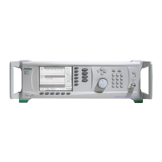
Anritsu MG369 B Series Manuals
Manuals and User Guides for Anritsu MG369 B Series. We have
1
Anritsu MG369 B Series manual available for free PDF download: Maintenance Manual
Anritsu MG369 B Series Maintenance Manual (282 pages)
Synthesized Signal Generators
Brand:
Anritsu
| Category:
Portable Generator
| Size: 7.12 MB
Table of Contents
Table of Contents
5
Chapter 1-General Information
11
Scope of Manual
11
Introduction
11
Description
11
Identification Number
11
Online Manual
11
Related Manuals
12
Operation Manual
12
GPIB Programming Manual
12
SCPI Programming Manual
12
Options
12
Contacting Anritsu
12
Level of Maintenance
13
Troubleshooting
13
Repair
13
Calibration
13
Preventive Maintenance
13
1-10 ESD Requirements
13
Preventive Maintenance
14
1-12 Startup Configurations
15
1-13 Test Equipment List
16
Chapter 2-Functional Description
21
Introduction
21
Major Subsystems
21
Digital Control
21
Front Panel Assembly
21
Frequency Synthesis
22
A9 YIG Assembly
22
Alc/Am/Pulse Modulator
22
RF Deck
22
Power Supply
22
Inputs/Outputs
23
Motherboard/Interconnections
23
Frequency Synthesis
26
Phase Lock Loops
26
Overall Operation
26
RF Outputs 0.01 Mhz to 65 or 67 Ghz
30
Hz to 10 Mhz (Option 22)
30
To 2.2 Ghz (Option 4)
30
To 2 Ghz (Option 5)
30
To 30 Ghz (Model MG3693B)
30
To 40 Ghz (Model MG3694B)
30
To 50 Ghz (Model MG3695B)
30
To 65 or 67 Ghz (Model MG3696B)
30
Frequency Modulation
31
Phase Modulation
31
Analog Sweep Mode
31
Step Sweep Mode
32
Alc/Am/Pulse Modulation
32
ALC Loop Operation
32
External Leveling
32
ALC Slope
33
Power Sweep
33
Amplitude Modulation
33
Pulse Modulation Operation
33
Pulse Generator Operation
33
RF Deck Assemblies
34
RF Deck Configurations
34
YIG-Tuned Oscillator
34
RF Signal Filtering
34
To 2 Ghz down Converter (Option 5)
35
To 2.2 Ghz Digital down Converter (Option 4)
35
Switched Doubler Module
35
Source Quadrupler Module
36
Model MG3695B SQM Operation
36
Model MG3696B SQM Operation
36
Step Attenuators
36
Chapter 3-Performance Verification
49
Introduction
49
Test Records
49
Connector and Key Notation
49
Test Equipment List
50
Measurement Uncertainty
53
Internal Time Base Aging Rate Test (Optional)
53
Internal Time Base Aging Rate Test with Absolute Time Model 300
54
Internal Time Base Aging Rate Test with Symmetricom (Datum) Model 9390-9600
55
Spurious Signals Test
56
Harmonic Test Initial Setup Procedure
56
Harmonic Test Procedure
56
Non-Harmonic Initial Setup Procedure
57
Non-Harmonic Test Procedure
58
Single Sideband Phase Noise Test
60
Agilent E5052B Signal Source Analyzer and E5053A down Converter
60
Test Setup
60
Test Procedure
62
Aeroflex PN9000 Phase Noise System
65
Test Setup
66
Test Procedure
66
Power Level Accuracy and Flatness Tests
70
Test Setup
70
Power Level Log Conformity
71
Power Level Accuracy (≥ -50 Dbm)
72
Test Setup
73
Test Procedure
74
Power Level Flatness
76
Test Setup
76
Test Procedure
77
Maximum Leveled Power
78
Test Setup
78
Test Procedure
79
3-10 Frequency Modulation and Phase Modulation Tests
80
Test Setup
80
Locked FM Accuracy
80
ΦM Accuracy
84
FM/ΦM Flatness and Bandwidth
88
Test Setup
88
Modulation Index Calculations
92
Unlocked Narrow FM Accuracy
94
Test Setup
94
Test Procedure
94
Amplitude Modulation Tests
96
Test Setup
96
External am Accuracy
97
Internal am Accuracy
98
AM Roll off
99
AM Flatness
101
3-12 Pulse Modulation Tests
103
Test Setup
103
Pulse Rise Time, Fall Time and Overshoot
104
Pulse Power Accuracy
106
Pulse On/Off Ratio
107
Test Setup
108
Test Procedure
108
Chapter 4-Adjustment
109
Introduction
109
Test Equipment List
109
Test Records
112
Subassembly Replacement
113
Connector and Key Notation
114
Initial Setup
114
Interconnection
114
PC Setup
115
Preliminary Calibration
117
Equipment Setup
117
Calibration Steps
117
Alternate 10 Mhz Reference Oscillator Calibration
119
Frequency Synthesis Tests
120
Test Setup
120
Coarse Loop/Yig Loop
120
Fine Loop
122
Switched Filter Shaper
123
Equipment Setup
123
Log Amplifier Zero Calibration
123
Limiter DAC Adjustment
124
Shaper DAC Adjustment
125
4-10 RF Level Calibration
125
Equipment Setup
129
ALC Bandwidth Calibration
130
Equipment Setup
130
Bandwidth Calibration
130
ALC Slope Calibration (Option 6 Only)
131
Equipment Setup
131
ALC Slope DAC Adjustment (Only for Units with Option 6 Analog Sweep)
131
4-13 am Calibration
134
Equipment Setup
134
AM Calibration Procedure
135
4-14 Frequency and Phase Modulation Calibration
137
Equipment Setup
137
FM Calibration Procedure
138
Chapter 5-Troubleshooting
143
Introduction
143
Test Equipment List
143
Error Messages
143
Self-Test Error Messages
143
Normal Operation Error and Warning/Status Messages
145
No Error Message
147
Troubleshooting Tables
148
Chapter 6-Removal And Replacement Procedures
175
Introduction
175
Replaceable Parts
175
Calibration and Verifications after Replacing an Assembly
178
Chassis Covers
181
Tool Required
181
Preliminary
181
Procedure
181
Front Panel Assembly
183
Preliminary
183
Procedure
183
A2 Microprocessor PCB Board
184
Preliminary
184
Procedure
184
A3 Reference/Fine Loop PCB
185
Preliminary
185
Procedure
185
A4 Coarse Loop PCB
186
Preliminary
186
Procedure
186
A5 to A13 PCB Removal
188
Preliminary
188
Card Cage Cover
188
A5 Auxiliary PCB
189
A6 Alc Pcb
189
A7 YIG Lock PCB
190
A9 YIG Assembly
190
A13 Pulse Generator PCB
190
6-10 Power Supply Assembly
191
Preliminary
191
Power Supply Top Assembly
191
12 Volt Standby Power Supply PCB
192
A20 Power Supply Regulator
193
Appendix A-Test Records
195
Introduction
195
Uncertainty Specifications
195
Test Records
195
Internal Time Base Aging Rate Test (Optional
196
Harmonics and Harmonically Related Signal Test Records
197
Harmonics and Harmonically Related Signal Test Records
198
Non-Harmonics Signal Test (All Mg369Xb Models
201
Non-Harmonics Signal Test (All Mg369Xb Models
202
Single Sideband Phase Noise Test with Agilent E5052B Signal Source Analyzer and E5053A down Converter
207
Single Sideband Phase Noise Test: Power Line and Fan Rotation Emissions with Agilent E5052B Signal Source Analyzer
216
And E5053A down Converter
218
Single Sideband Phase Noise Test with
219
Aeroflex PN9000 Phase Noise System
219
Single Sideband Phase Noise Test: Power Line and Fan Rotation Emissions with Aeroflex PN9000 Phase Noise System
228
Power Level Log Conformity Test
232
Power Level Accuracy Test
233
Power Level Flatness Test
247
Maximum Leveled Power Test
251
Frequency Modulation Test
258
Amplitude Modulation Test
263
Pulse Modulation Test
267
Preliminary Calibration
270
Frequency Synthesis Test (1
271
Switched Filter Shaper Calibration
274
RF Level Calibration
274
ALC Bandwidth Calibration
274
ALC Slope Calibration
274
AM Calibration
275
FM Calibration
275
Appendix B-Technical Data Sheet
277
Mg369Xb Technical Data Sheet
277
Index
279
Advertisement
Advertisement
Related Products
Anritsu MG3690A
Anritsu MG369 Series
Anritsu MG3692B
Anritsu MG3693B
Anritsu MG3696B
Anritsu MG3695C
Anritsu MG369XA Series
Anritsu MG369XB Series
Anritsu MG3690B
Anritsu MG3694B
Anritsu Categories
Measuring Instruments
Test Equipment
Portable Generator
Control Unit
Thermometer
More Anritsu Manuals
Login
Sign In
OR
Sign in with Facebook
Sign in with Google
Upload manual
Upload from disk
Upload from URL