Sign In
Upload
Manuals
Brands
Amsco Manuals
Laboratory Equipment
60 H
Amsco 60 H Steam Sterilizer Equipment Manuals
Manuals and User Guides for Amsco 60 H Steam Sterilizer Equipment. We have
1
Amsco 60 H Steam Sterilizer Equipment manual available for free PDF download: Operator's Manual
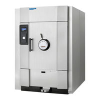
Amsco 60 H Operator's Manual (152 pages)
Medium Steam Sterilizers
Brand:
Amsco
| Category:
Laboratory Equipment
| Size: 8 MB
Table of Contents
Table of Contents
7
1 Safety Precautions
15
2 Symbols and Labels
19
Table 2-1. Symbol Definitions
19
Table 2-2. Label Definitions
20
3 Installation Verification
23
Service Clearance
23
Plumbing Services
23
Electrical Service
24
Sterilizer Final Check
24
Cycle Operation
24
Technical Specifications
25
Overall Size
25
Weight (Fully Loaded)
25
Utility Requirements
26
Environmental Conditions
26
4 Techniques of Sterilization
27
General
27
Control Measures for Verifying Sterilization Process
28
Biological Monitors
28
Testing for Prevacuum Efficiency
29
Bowie-Dick Test
29
Vacuum Leak Test
30
Recommendations for the Sterilization Process
30
Techniques of Sterilization for Liquid Cycle
31
Table 4-2. Liquid Cycle Processing Guidelines
31
Recommendations for Sterilizing Liquids
32
Figure 4-1. Vented Closures
32
5 Component Identification
33
General
34
Main Sterilizer and Cycle Controls
34
Figure 5-2. Location of Sterilizer Utility Controls
34
Figure 5-3. Utility Supply Valves and Standby Screen
35
Control Displays
36
Figure 5-4. Typical Out-Of-Cycle and In-Cycle Displays
36
Alarm Displays
37
Figure 5-5. Typical Alarm Displays
37
Operating End and Non-Operating End Control Panels
38
Figure 5-6. Operating End and Non-Operating End Control Panels
38
Cycle Selection Touch-Screen Pads
39
Figure 5-7. Cycle Selection Touch Pads
39
Figure 5-8. Values Touch Screen Pads
40
Values Touch-Screen Pads
40
Abort Touch-Screen Pad
41
Figure 5-9. Cycle Abort Touch-Screen Pad
41
Printer
42
Printouts
42
Figure 5-10. Typical Printout
43
Horizontal-Sliding Door Operation
44
Hinged-Door Operation
44
Figure 5-11. Hinged Door Operation
44
Emergency Door Opening Procedure
45
Figure 5-12. Chamber and Seal Emergency Exhaust Valves
45
Figure 5-13. Operate Lock Release Lever
46
Emergency Stop Switch
47
Figure 5-14. Emergency Stop Button, Key and Guard
47
Figure 5-15. Press Abort Button to End Cycles When Needed
47
Emergency Stop Guard
48
Emergency Stop Key
48
Emergency Stop Label
48
Figure 5-16. Emergency Stop Label
48
6 Sterilizer Operation
49
Before Operating the Sterilizer
49
Figure 6-1. Utility Supply Valves and Basic Sterilizer Controls
50
Preparing Loads for Sterilization Cycles
51
Guidelines for Placement of Various Loads
51
Unloading the Sterilizer
52
Loading Cart and Transfer Carriage Instructions: Loading
53
Figure 6-2. Align Loading Car with Chamber Opening
53
Loading Car Instructions: Unloading
54
Loading/Unloading Sterilizer: Rack and Shelves
54
Prevacuum Sterilizer Cycles
55
Figure 6-3. Sterilizer Chamber Equipped with Rack and Shelves
55
Table 6-1. Factory-Set Prevacuum Cycles
56
Prevac Cycles
57
Figure 6-5. Typical Prevacuum Cycle Printouts
58
Table 6-2. Factory-Set Gravity Cycles and Cycle Values
60
Gravity Cycles
61
Figure 6-7. Typical Gravity Cycle Printout
62
Table 6-3. Factory-Set Optional Liquid Cycle and Cycle Values
64
Liquid Cycle
65
Figure 6-9. Typical Printout of a Liquid Cycle
66
Test Cycles
68
Table 6-4. Test Cycles
68
Bowie-Dick Test Cycle
69
Figure 6-11. Dart (Bowie-Dick) Test Cycle Printout
71
Vacuum Leak Test
72
Figure 6-12. Typical Printout of a Leak Test Cycle
73
Aborting Cycles
74
Cycle Graphs
75
Figure 6-13. Cycle Graph - 270°F or 275°F Prevacuum and Dart (Bowie-Dick) Cycles
75
Figure 6-14. Cycle Graph - Gravity Cycle
75
Figure 6-15. Cycle Graph - Leak Test
76
Figure 6-16. Cycle Graph - Steam Flush Pressure Pulse (SFPP) Cycles
76
Figure 6-17. Cycle Graph - Liquid Cycle
77
7 Cycle and Control Value Programming
79
Change Values
79
Change Cycle Values
80
Overview
80
Adjusting Cycle Sterilize Time and Dry Time
80
Table 7-1. Adjustment Ranges for Cycle Values
82
Step-By-Step Flowchart
83
Entering Custom Cycle Names
86
Figure 7-4. Enter or Change Custom Cycle Names
86
Change Time and Date
87
Change Machine Setup
90
Table 7-2. Change Machine Setup
90
Access Code
91
Lockout
93
Utilities Control
95
Machine Number
99
Time Format
99
Print Format
100
Figure 7-5. Sample Full and Condensed Printouts
102
Audible Signals
103
Date Format
104
Units
104
Duplicate Print
105
Leaving Change Values
106
8 Routine Maintenance
107
Preventive Maintenance
107
Printer Maintenance
108
Check Printer Paper Supply
108
Figure 8-1. Open Printer Door
108
Figure 8-2. Printer Components (Printer Door Open)
108
Figure 8-3. Tear Printer Paper
109
Figure 8-4. Insert New Paper Roll
109
Figure 8-5. Insert Paper Behind Printer Ink Cartridge
110
Figure 8-6. Press Paper Feed Button to Advance Paper
110
Figure 8-7. Coil Paper Onto Take-Up Spool
110
Check Printer Ink Cartridge
111
Figure 8-8. Reinstall Take-Up Spool
111
Figure 8-9. Remove Ink Cartridge from Printer
111
Figure 8-10. Slip Cartridge Onto Printer Paper
112
Routine Chamber Maintenance
113
Clean Chamber Drain Strainer
113
Figure 8-11. Chamber Drain Strainer
113
Flush Chamber Drain
114
Clean Chamber
115
9 Troubleshooting
117
General
117
Typical Alarm Screen
117
Figure 9-1. Typical Alarm Screen
117
Typical Alarm Printout
118
In-Cycle Alarms
118
Too Long in Charge
118
Figure 9-2. Typical Alarm Printout
118
Too Long in Exhaust
119
Too Long in Evacuation
119
Too Long in Air Break
120
Under Sterilize Temperature
121
Over Sterilize Temperature
122
Door Unsealed
123
Chamber Pressure/Temperature Failure
123
Exhaust Rate too Fast
124
Exhaust Rate too Slow
125
Recorder Deviation Alarm
125
Out-Of-Cycle Alarms
126
Too Long to Close Door
126
Too Long to Open Door
127
Pressure in Chamber
127
Waste Temperature Probe Failure
128
Atmospheric Pressure Alarm
129
Input/Output Board #1 Communication Failure
129
Relay #1 Failure
130
ROM Failure
130
RAM Failure
131
ADC Failure
131
Sensor Alarms
132
Water in Chamber
132
Too Long in Jacket Charge
132
Too Long to Seal Door
133
Too Long to Unseal Door
134
Chamber Pressure Transducer Failure
134
Chamber Temperature Probe Failure
135
Jacket Temperature Probe Failure
136
Door Switch Failure
136
Door Seal a Switch Malfunction
138
Board Overtemp Failure
139
10 Service Procedures
141
General
141
Air Filter Replacement
141
Clean Strainers
142
Figure 10-1. Serviceable Piping Components
143
Figure 10-2. Remove Door Seal
144
Figure 10-3. Location of Seal Lot Data and Reference Indicators
144
Door Seal Replacement Procedure
145
Steam Trap Replacement
146
Clean or Replace Piping Check Valves
146
Rebuild Solenoid Valves
146
Figure 10-4. Steam Trap
146
Safety Valve Test
147
Figure 10-5. Internal Pilot-Operated Solenoid Valve
147
Recommended Spare Parts
148
Waste Products Disposal
150
Figure 10-6. Piping Schematic - AMSCO 400 Series Medium Steam Sterilizer
151
Advertisement
Advertisement
Related Products
Amsco 60 SL
Amsco 110LS
Amsco 250LS
Amsco 36 H
Amsco 36 SL
Amsco 400 Series
Amsco 48 H
Amsco 48 SL
Amsco C Series
Amsco Century
Amsco Categories
Laboratory Equipment
Medical Equipment
Washer
Light Fixture
More Amsco Manuals
Login
Sign In
OR
Sign in with Facebook
Sign in with Google
Upload manual
Upload from disk
Upload from URL