Sign In
Upload
Manuals
Brands
AMPURE Manuals
Battery Charger
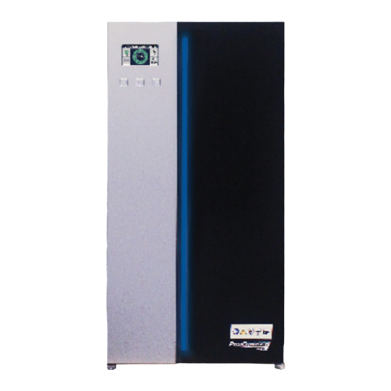
PosiCharge ProCore Edge 9
AMPURE PosiCharge ProCore Edge 9 Manuals
Manuals and User Guides for AMPURE PosiCharge ProCore Edge 9. We have
2
AMPURE PosiCharge ProCore Edge 9 manuals available for free PDF download: Installation, Operation & Service Manual, Installation Manual
AMPURE PosiCharge ProCore Edge 9 Installation, Operation & Service Manual (88 pages)
Brand:
AMPURE
| Category:
Battery Charger
| Size: 3 MB
Table of Contents
Table of Contents
5
Warnings and Cautions
11
Installation and Operation
13
Acronyms, Abbreviations and Symbols
14
Required Tools
17
Technical Specifications for 48V and 80V Modules Fitted to
17
Three-Bay and Five-Bay Cabinets
17
Positioning the Charger
19
Fig. 1 - Attaching Points for M8 Lifting Eyebolts, Top Panel View
19
Choosing to Wall-Mount or Floor-Mount the Charger
20
Wall Mount Installation
20
Fig. 2 - Charger, Wall, Wall Mount Hanger, Bottom Bracket and
20
Fig. 3 - Bolt Hole Locations
21
Fig. 4 - Bracket Slots
21
Fig. 5 - L Bracket
21
Floor Mount Installation
22
Fig. 6 - Floor Mount Stand
22
Fig. 7 - Eight Floor Stand Anchor Bolting Points Are Provided
23
Fig. 8 - Size Reference
23
Fig. 10 - Backside of Floor Mounting Sand
24
Fig. 9 - Bracket Slots
24
Fig. 11 - Charger Underside and L Bracket
25
Remote Battery Connections (Optional)
26
Fig. 12 - Ten-Way Screw Terminal Connector
26
Fig. 13 - Battery Communication Wires Connected to the
27
Charger Light Bar
30
Operating Instructions
32
Fig. 14 - Status Bar
32
Battery Display
33
Fig. 15 - Graphical Battery Display
33
Alternate Battery Display
36
Fig. 16 - Alternate Tabular Battery Display
37
Faults and Warnings - Hardware Diagnostics
39
Initial Software Setup
45
Required Equipment
46
Procedure
46
Fig. 17 - USB Cable AB
46
Fig. 20 - Update Firmware Tab
47
Fig. 19 - Comm Port
47
Fig. 21 - Terminal Tab
48
Service / Maintenance
49
Preventative Maintenance Schedule
49
Replacing a Module
53
Fig. 22 - Latch on the Side of the Charger
53
Fig. 23 - Disconnected Power Cables
54
Fig. 24 - Ground Cable Disconnection
55
Fig. 25 - Single Cable Connection
56
Fig. 26 - Multi-Cable Connection
57
Fig. 27 - Power Module Removal
58
Fig. 28 - Replacement Power Module Insertion
59
Fig. 29 - Power Module Position Selector
60
Fig. 30 - Power Module Positions
60
Fig. 31 - Flat Cable Reconnection to the Power Module
61
Fig. 32 - Flat Cable Connection to the Terminal Block
62
Fig. 33 - Reconnected DC Output Power Cable
63
Fig. 34 - Reconnected Ground Cable and AC Input Power Cable
63
Replacing the Output Cable
65
Fig. 35 - Torx TX25 Screws Securing the DC Output
65
Fig. 36 - Three- and Five-Bay Bus Bar Arrangement
66
Replacing the Controller PCBA
69
Fig. 37 - Controller PCBA
69
Fig. 38 - PCBA 3/4 View
70
Fig. 39 - PCBA Rear Facing View
70
Replacing the Door Panel
71
Removal
71
Fig. 40 - Inside Cabinet View
71
Fig. 41 - Outside Cabinet View
71
Fig. 42 - Alignment Pin
72
Fig. 43 - Replacement Door
72
Fig. 44 - Cable Clamp
73
Fig. 45 - New Clamp
73
Installation
74
Fig. 46 - M4 Bolts
74
Fig. 47 - Align the Pin
74
Fig. 48 - M4 Bolts
74
Interface Board Communication Connectors / Replacing the Fuse
75
Fig. 49 - Torx Screws
75
Fig. 50 - Mating Connectors
76
Fig. 51 - Interface Board Screws
77
Fig. 52 - Fuse
78
Fig. 53 - Interface Board
78
Firmware Updates
79
Fig. 54 - Software App
79
Adding the AVB File
80
Fig. 55 - Selecting an AVB File
80
Managing AVB Files
81
Fig. 56 - Selecting Target Devices
81
Uploading Software
82
Fig. 57 - Uploading Software
82
Voltage Driven Vs BMID Communications
83
Default Battery Setup for Voltage-Mode Charging
83
Fig. 58 - Default Battery Setup
83
Fig. 59 - Default Battery Setup
84
Advertisement
AMPURE PosiCharge ProCore Edge 9 Installation Manual (41 pages)
Brand:
AMPURE
| Category:
Battery Charger
| Size: 2 MB
Table of Contents
Table of Contents
4
Installation Guide
5
Technical Specifications
5
Installation
7
Standard Side-To-Side Charger Spacing
7
Installation Precautions
7
Positioning the Charger
8
Wall Mount Installation
8
Floor Stand Installation
9
Connection to Main Power
9
Risk of Fire
9
3.7 - DC Battery Connection
11
Risk of Electric Shock
11
Guide D'installation
17
Spécifications Techniques des Modules 48 et 80 Volts Équipés D'armoires à Trois ou Cinq Baies
17
Installation
20
Espacement Latéral Standard des Chargeurs
20
Précautions D'installation
20
Figure 1 Conception du Flux D'air Latéral, Vue de Dessus; et Espacement Latéral Standard des Chargeurs
20
Positionnement du Chargeur
21
Installation Murale
21
Figure 2 Points de Fixation des Boulons à Œil de Levage M8, Vue du Panneau Supérieur
21
Figure 3 Chargeur, Mur, Support Mural, Support Inférieur et Vis à Filetage M6
21
Figure 7 Trous Pré-Percés pour la Fixation de la Base au Sol
21
Figure 9 Chargeur Accroché au Support au Sol
21
Installation du Support au Sol
22
Connexion de L'alimentation CA
22
Figure 4 Chargeur Sur le Support Mural
22
Figure 5 Support Inférieur Monté Sur le Chargeur
22
Figure 6 Support au Sol
22
Figure 8 Bâton Pogo (en Option) Fixé au Support Pogo
22
Figure 10 Support Inférieur Monté Sur le Chargeur et le Support au Sol
22
Figure 11 Entrée de Service CA
23
Figure 12 Entrée de Service CA pour L'armoire à Trois Baies
23
Figure 13 Entrée de Service CA pour L'armoire à Cinq Baies
23
Connexion de L'alimentation CC
25
Risque de Choc Électrique
25
Inglés (EE. UU.)
32
Guía de Instalación
32
Especificaciones Técnicas para Módulos de 48 y 80 Voltios
32
Equipados con Gabinetes de Tres O Cinco Bahías
32
Instalación
34
Espacio Estándar del Cargador de Lado a Lado
34
Precauciones de Instalación
34
Lado
34
Colocar el Cargador
35
Instalación de Montaje en Pared
35
Figura 2 Puntos de Fijación para Armellas de Elevación M8, Vista del Panel Superior
35
Figura 3 Cargador, Pared, Soporte de Montaje en Pared, Soporte Inferior y Tornillo con Rosca M6
35
Figura 8 Pogo Stick (Opcional) Acoplado al Soporte del Pogo
36
Figura 9 Cargador Colgado en el Soporte del Piso
36
Figura 10 Soporte Inferior Montado en el Cargador y el Soporte de Piso
36
Figura 4 Cargador en el Soporte de Montaje en Pared
36
Instalación de Soporte de Suelo
36
Figura 6 Soporte de Suelo
36
Figura 7 Orificios Pretaladrados para Atornillar la Base al Piso
36
Conexión de Alimentación de CA
36
Riesgo de Incendio
36
Figura 5 Soporte Inferior Montado en el Cargador
36
Figura 11 Entrada de Servicio de CA
37
Figura 12 Entrada de Servicio de CA para el Gabinete de Tres Bahías
37
Figura 13 Entrada de Servicio de CA para el Gabinete de Cinco Bahías
37
Conexión de Batería de CC
38
Riesgo de Descarga Eléctrica
39
Francés (Canadá)
40
Advertisement
Related Products
AMPURE PosiCharge ProCore Edge 15
AMPURE PosiCharge ProCore Edge 30 North America
AMPURE PosiCharge ProCore
AMPURE POSICHARGE DVS100
AMPURE POSICHARGE DVS150
AMPURE TurboCord 240V
AMPURE Categories
Battery Charger
Automobile Accessories
More AMPURE Manuals
Login
Sign In
OR
Sign in with Facebook
Sign in with Google
Upload manual
Upload from disk
Upload from URL