Sign In
Upload
Manuals
Brands
Ampcontrol Manuals
Controller
ROCKSTARTER
Ampcontrol ROCKSTARTER Manuals
Manuals and User Guides for Ampcontrol ROCKSTARTER. We have
2
Ampcontrol ROCKSTARTER manuals available for free PDF download: User Manual, Firmware Update User Manual
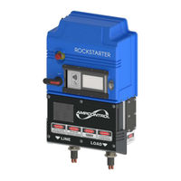
Ampcontrol ROCKSTARTER User Manual (132 pages)
Multifunction Outlet Starter
Brand:
Ampcontrol
| Category:
Controller
| Size: 6 MB
Table of Contents
Copyright Notice
3
Before You Begin
3
Table of Contents
4
Safety and Other Warnings
11
Safe Use of Equipment
11
Supplementary Documentation
11
Requirements for Safe Operation
12
Receiving and Storage
13
Receiving
13
Inspection
13
Transportation
13
Figure 1: Strapping Considerations
13
Storage after Delivery
14
Unpacking of Equipment
14
Product Description
15
Overview
15
Features
15
Application
16
Figure 2: Rockstarter Overview
16
Configuration Examples
17
Figure 3: Rockstarter Overview - Two Rockstarters with One Incoming Feed
17
Figure 4: Rockstarter Overview - Four Rockstarters with Two Incoming Feeds
17
Arc Fault Mitigation
18
Figure 5: Example of Rockstarter Label
18
Installation
19
General Warnings
19
Mandatory Installation Practices
19
Mechanical Installation Information
20
Figure 6: Rockstarter Dimensions (MM)
20
Table 1: Rockstarter Dimensions
20
Figure 7: Rockstarter Lifting Adaptor
21
Figure 8: Rockstarter Wall Bracket Mount
22
Figure 9: Mounting Bracket Clamps
22
Figure 10: Rockstarter Terminal Compartment Cover Overview
24
Figure 11: Rockstarter Adaptor Plate (60A Pictured)
25
Figure 12: Dual Gland J-Box
26
Figure 13: Dual Incomer Termination
27
Figure 14: Dual Connection Side Entry Box
28
Figure 15: through Feed - with (Left) & Without (Right) Cover
29
Figure 16: Ethernet & Terminal I/O Connector
30
Table 2: Terminal I/O Connector Pinout
30
Figure 17 the Fan Sequencing Cable (181876)
31
Figure 18 the Sequencing Tee Cable (195515)
31
Figure 19: Load Connection Module (LCM) (MM)
32
Figure 20: Float Junction Box (196069)
33
Table 3: LCM Pinout
33
Figure 21: H3RO Fibre Communications Junction Box Complete with Terminals (192139)
34
Electrical Installation Information
35
Figure 22: Electrical Connection Diagram
35
Figure 23: Incoming Pilot - Terminations
36
Figure 24: Incoming Pilot - through Terminations
36
Figure 25: Outgoing Pilot - Terminations
37
Figure 26: Remote Stop/Start
37
Figure 27: Load Connection Module (LCM) - Connection Diagram
38
Figure 28: Control Supply Termination
39
Commissioning
40
Earth Leakage
40
Earth Continuity
40
Earth Fault Lockout
40
Insulation Test (High Voltage)
41
Main Contactor Fail
41
Voltage Measurement
41
Load Connection Module (LCM)
41
Pump Protection Test
41
Fan Protection Test
41
Remote Stop Test
41
Remote Start Test
42
Emergency Stop
42
Product Operation
43
Interfacing Elements
43
Figure 29: Rockstarter UI Interface
43
Figure 30: Rockstarter UI - Home Screen
44
Table 4: Outlet State
44
Table 5: Outlet Control
45
Table 6: Outlet Status Icons
46
Table 7: Trip Messages
46
Figure 31: Rockstarter UI - Testing Screen
48
Figure 32: Rockstarter UI - Outlet Test System
49
Figure 33: Rockstarter UI - Status Screen
50
Table 8: OTS Status Symbols
50
Table 9: Status Page Overview
51
Figure 34: Rockstarter UI - SETUP Page
54
Figure 35: Rockstarter Lighting
55
Table 10: Rockstarter Lighting Overview
55
Outlet Starting
56
Outlet Resets
57
Internal Trips
58
Event Log
58
Table 11: Event Log Entry Types
58
Time and Date
60
Modbus TCP
60
Remote Desktop Access
60
Outlet Control
61
Outlet Configuration
61
Figure 36: Rockstarter UI - Mode Control
62
Fan Control Mode
63
Table 12: Fan Protection - Configuration Settings
64
Table 13: Rockstarter Burp Timing Mode
64
Figure 37: Starting Options - Post Blast Start Enabled, Remote Start Disabled
65
Table 14: Fan Incremental Timing Mode
65
Figure 38: Starting Options - Post Blast Start and Delayed Start Enabled, Remote Start Disabled
66
Pump Control Mode - (Anti Snore Mode)
67
Table 15: Pump Protection - Configuration Settings
67
Table 16: Rockstarter Pump Sleep Timing Mode
67
Table 17: Pump Incremental Timing Mode
68
Figure 39: Starting Options - Pump Mode
69
Touch Potential Protection Functions
70
Earth Leakage
70
Table 18: Earth Leakage Trip Characteristics
70
Earth Continuity
71
Table 19: Earth Leakage CT Failure Trip Characteristics
71
Table 20: Earth Continuity Series Trip Characteristics
72
Table 21: Earth Continuity Shunt Trip Characteristics
72
Figure 40: Starting Options - Normal Mode
74
Earth Fault Lockout
75
Table 22: Earth Fault Lockout Trip Characteristics
75
Table 23: EFLO Trip Threshold
75
Main Contactor Protection
76
Table 24: Voltage Detection Trip Characteristics
76
Table 25: Frozen Contactor Trip Characteristics
77
Table 26: Contactor Close Fail Trip Characteristics
77
Table 27: External Open Trip Characteristic
78
Table 28: Coil Voltage Detection Trip Characteristics
78
Load Related Protection Functions
79
Inverse Time Protection
79
Table 29: Overcurrent Trip Characteristics
80
Table 30: Motor Overload Trip Characteristics
83
Short Circuit
87
Table 31: Short Circuit Trip Characteristics
87
Undervoltage
88
Current Imbalance
88
Table 32: Undervoltage Trip Characteristics
88
Table 33: Current Imbalance Trip Characteristics
88
Undercurrent
89
Table 34: Undercurrent Trip Characteristics
89
Service, Maintenance & Disposal
90
Equipment Service
90
Equipment Maintenance
91
Disposal
91
Accessories & Spare Parts
92
Accessories
92
Figure 41: Rockstarter Mounting Frame C/W Bolts - PN: 177190
92
Figure 42: Rockstarter Mounting Bar Kit - PN: 177191
92
Figure 43: Rockstarter Adaptor Plates - 60A Left (PN: 179292) & 150A Right (PN: 181811)
93
Figure 44: Feed through Kit - 181441
93
Figure 45: Junction Box Dual Gland
94
Figure 46: Dual Incomer: Option 1 Flexible Busbar
95
Spare Parts
97
Figure 48: Rockstarter Gland Plate & Feed through Kits
97
Figure 49: Rockstarter Terminal Cover Kit
98
Figure 50: Rockstarter Secondary Covers
99
Figure 51: Rockstarter Capacitive Touch Panel Kit
100
Specifications
101
Equipment List
104
Rockstarter & Accessories
104
Rockstarter Spares
106
Appendix A: Protection Element Load Current Tables
108
A1: Protection Module Full Load Current Table
108
A2: Protection Module TMS Table
109
Appendix B: Rockstarter Modbus Tcp
110
B1 Outlet Control Registers
110
B2 Outlet Live Data
110
B3 UI Live Data - Fan Mode
114
B4 UI Live Data - Pump Mode
115
B5 UI Live Data - Outlet Mode
115
B6 UI Live Data - Common
116
B7 Outlet Parameters
117
B8 RKS Load Parameters - Diode Mode
118
B9 RKS General Parameters - Diode Mode
122
B10 RKS Load Parameters - LCM Mode
127
B11 RKS General Parameters - LCM Mode
128
Appendix C: Hmi Replacement
129
Figure 52: Replacing the Display Glass and Digitiser
129
Appendix D: Drawings
130
Advertisement
Ampcontrol ROCKSTARTER Firmware Update User Manual (12 pages)
Multifunction Outlet Starter
Brand:
Ampcontrol
| Category:
Controller
| Size: 0 MB
Advertisement
Related Products
Ampcontrol iMac
Ampcontrol imac itools
Ampcontrol Categories
Relays
Controller
Accessories
Measuring Instruments
UPS
More Ampcontrol Manuals
Login
Sign In
OR
Sign in with Facebook
Sign in with Google
Upload manual
Upload from disk
Upload from URL