Sign In
Upload
Manuals
Brands
Ametek Manuals
Power Supply
Sorensen XG 100-8.5
Ametek Sorensen XG 100-8.5 Manuals
Manuals and User Guides for Ametek Sorensen XG 100-8.5. We have
2
Ametek Sorensen XG 100-8.5 manuals available for free PDF download: Operating Manual
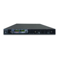
Ametek Sorensen XG 100-8.5 Operating Manual (399 pages)
XG Family Programmable DC 670 Watts – 1700 Watts
Brand:
Ametek
| Category:
Power Supply
| Size: 9 MB
Table of Contents
Table of Contents
9
Power Supply
1
Contact Information
3
Related Information
6
Important Safety Instructions
7
Table of Contents
19
Introduction
21
Features and Options
22
XG Models (Firmware Version 2.0 and Higher)
23
Table 1-1 XG 850 Watt Series Voltage and Current Ranges
23
Table 1-2 XG 1500 Watt Series Voltage and Current Ranges
24
Table 1-3 XG 1700 Watt Series Voltage and Current Ranges
24
Front Panel
25
Figure 1-1 XG Front Panels (Half Rack, Above; Full Rack, Below; Not To-Scale)
25
Figure 1-2 Front Panel Display and Controls
26
Front Panel Display and Controls
26
Rear Panel Connectors on 850 Watt Models
27
Figure 1-3 XG 850 Watt Units: 6 V to 40 V Models
27
Figure 1-4 XG 850 Watt Units: 60 V to 150 V Models
27
Figure 1-5 XG 850 Watt Units: 300 V to 600 V Models
27
Rear Panel Connector on 850 Watt Model
27
Rear Panel Connectors on 1500 and 1700 Watt Models
29
Figure 1-6 XG 1500 and 1700 Watt Units: 6 V to 40 V Models
29
Figure 1-7 XG 1500 and 1700 Watt Units: 60 V to 600 V Models
30
Installation
31
Basic Setup Procedure
32
Step 1: Inspecting and Cleaning
33
Initial Inspection
33
Periodic Cleaning
33
Step 2: Location and Mounting
34
Purchasing Rack Mount Kits
34
Rack Mounting
34
Ventilation
34
Rack Mount Kit Options
34
Step 3: Connecting Ac Input Power
35
XG 850 Watt AC Input Connector
35
Figure 2-1 1500 and 1700 Watt AC Input Cover and Strain Relief
36
Table 2-2 XG 1500 and 1700 Watt: Recommended AC Input Wire (Higher Power)
36
XG 1500 and 1700 Watt AC Input Connector
36
XG 1500 and 1700 Watt AC Input Wire
36
XG 1500 and 1700 Watt AC Input Wire Connection
37
Step 4: Selecting Load Wires
38
Current Carrying Capacity
38
Insulation Rating
38
Load Wiring
38
Table 2-3 Current Carrying Capacity for Load Wiring
38
Maximum Load Wiring Length for Operation with Sense Lines
39
Noise and Impedance Effects
39
Step 5: Performing Functional Tests
40
Powering the Power Supply On/Off
40
Voltage and Current Mode Operation Checks
41
Step 6: Connecting Loads
42
DC Output Connectors
42
Figure 2-3 Diode Placement
43
Inductive Loads and Batteries
43
Connecting Multiple Loads
44
Connecting Single Loads
44
Figure 2-4 Connecting Single Loads
44
Step 7: Connecting Remote Sensing
45
Figure 2-5 Remote Sense Connection
45
Local Operation
47
Introduction
48
Configuring Settings from the Front Panel
48
Figure 3-1 9-Position Mode Control
48
Using the 9-Position Mode Control
48
Using the Rotary Adjust/Enter Control
48
Coarse and Fine Adjustment Modes
49
Navigating the Menu System
50
Setting VOLTS and AMPS Modes
50
Normal Display Mode and Inactivity Timeout
52
Display Messages on the Front Panel
54
Table 3-2 Front Panel Display Text
54
Standard (Local) Operation
56
Operating Modes
56
Figure 3-3 Operating Modes
59
Shipped Configuration (Local Operation)
62
Enabling the Output
62
Table 3-3 Shipped Configuration
62
Enabling the Auxiliary Output
63
Output Auto Start Mode (Auto Restart)
63
Auxiliary Auto Start Mode
64
Constant Power Mode (Version 2.21 and Higher)
64
Alarms and Errors
66
Alarm and Error
66
Clearing Alarms
67
Front Panel ALARM LED
68
Alarm Masking
69
Table 3-5 Alarm Mask Bit Positions
69
Alarm Output Latching
70
Table 3-6 Alarm Latch Bit Positions
70
Setting Foldback Mode
71
Resetting Activated Foldback Protection
72
Using over Voltage Protection (Ovp)
73
Defining the OVP Set Point
74
Using under Voltage Protection (Uvp)
75
Defining the UVP Set Point
75
Over Current Protection (Ocp)
76
Using over Temperature Protection Lock (Otp)
77
Defining the OTP Mode
77
Resetting in Latch Mode
77
Using the External Shutdown Function
78
Activating the External Shutdown Function
78
Controlling the External Shutdown Function
78
Defining the Polarity of the External Shutdown Signal
79
Loop Protection (Version 2.21 and Higher)
79
Setting up Loop Protection
80
Interlock Function
81
Defining the Interlock Mode
81
Output Protection
81
Programming Voltage Output Preset
81
Programming Current Output Preset
82
Power on Status Signal
83
Hardware Malfunction Alarms
83
Current Configuration Memory Settings
84
Table 3-7 Power Cycle Saved/Recalled Settings
84
User Setting Memory Locations
85
Table 3-8 User Accessible Saved/Recalled Settings Voltage Setpoint
85
Recalling User Setting Memory Locations
86
Saving User Setting Memory Locations
86
Local Lockout
87
Disabling Local Lockout
87
Enabling Local Lockout
87
Resetting the Power Supply
88
Table 3-9 Power Supply Default Settings
88
Using Multiple Power Supplies
90
Figure 3-4 Split Supply Operation
91
Configuring Multiple Supplies for Series Operation
92
Figure 3-5 Series Operation
93
Figure 3-6 Load Connections in Remote Sensing Mode
94
Configuring Multiple Supplies for Current Sharing Operation (APG Method)
95
Connecting to the Load in Local Sensing Mode (Parallel Control Method)
97
Figure 3-7 Load Connections in Local Sensing Mode
97
Connecting to the Load in Remote Sensing Mode (Parallel Control Method)
98
Figure 3-8 Load Connections in Remote Sensing Mode (Parallel Control Method)
98
Analog Programming (Apg) and Isolated Analog Programming (Isol)
101
Introduction
102
Analog Programming (APG) of Output Voltage and Output Current
102
Remote Programming Options
103
Table 4-1 Monitor Lines
103
Table 4-2 Remote Programming Options
104
Analog Programming (APG) Connector J1
105
Table 4-3 APG Pins and Functions J1
105
Figure 4-2 Inserting Screwdriver into Spring Terminal Block
107
Figure 4-3 APG and DC Output Connector
107
Analog Programming Mode
109
Analog Programming with External Voltage Source
109
Voltage-Controlled Voltage APG Setup
110
Voltage-Controlled Current APG Setup
112
Resistive-Controlled Voltage APG Setup
115
Resistive-Controlled Current APG Setup
117
Voltage and Current Readback
119
Isolated Analog Programming Mode (Isol)
120
AUX Output and Isolated Analog Programming (ISOL) Connector
120
Table 4-4 aux Output and ISOL Connector Pins and Functions J3
121
Voltage-Controlled Voltage ISOL Setup
123
Voltage-Controlled Current ISOL Setup
125
Resistive-Controlled Voltage ISOL Setup
128
Resistive-Controlled Current ISOL Setup
130
Voltage and Current Readback (Isolated)
132
Remote Operation
133
Introduction
134
Hardware and Connection Setup
134
Configuring Remote Control Using RS-232
134
Table 5-1 Remote Control Connector Pins and Functions J4 and J6
135
Table 5-2 DB-9 Pinouts
136
Table 5-3 RJ-45 Pinouts
136
Table 5-4 DB-25 Pinouts
137
Configuring Remote Control Using RS-485
139
Table 5-5 DB-9 Pinouts
139
Table 5-6 RJ-45 Plug Pinouts
139
Table 5-7 RJ-45 Plug on Slave Unit
140
Configuring Remote Control Using the USB Connector
141
Setting up the PC to Use the USB Connection
141
Figure 5-8 Install Hardware Device Drivers
142
Figure 5-10 Device Manager
144
Figure 5-11 Communications Port (COM1) Properties
145
GPIB Connector (Optional)
147
Table 5-8 GPIB Pin Description (J2)
147
Figure 5-13 Scanning for Instruments
149
Figure 5-14 Instrument Properties
150
Ethernet/Lan (ENET) Connector (Optional)
151
Multiple Power Supply Connections to RS-485 Bus
151
Terminal Configuration
153
Data Format
153
End of Message
153
Hyperterminal
153
Figure 5-16 USB Settings
154
Figure 5-17 ASCII Setup
155
Selecting the Appropriate Communication Port
156
Multichannel Address Setting
157
Remote Interface Addressing
158
Multichannel Commands Explained
159
Table 5-9 Rules for Multichannel Responses
159
Status Reporting in SCPI
161
Figure 5-18 SCPI Status Reporting Model
162
Status Registers Model from Ieee 488.2
163
Status Byte
164
Error/Event Queue (ERR)
164
Questionable Status Register Summary (QSR)
164
Master Summary Status (MSS)
165
Message Available (MAV)
165
Request Service (RQS)
165
Standard Event Status Summary (ESB)
165
Operation Status Register Summary (OSR)
166
Standard Event Status Register (SESR)
167
Figure 5-20 Summary of Standard Event Status Register
168
Standard Scpi Register Structure
170
Figure 5-21 SCPI Register Model
170
Operation Status Register
171
Figure 5-22 Operation Status Register Fanout
171
Table 5-12 Operation Status Register
172
Table 5-13 Operation Shutdown Status Register
173
Table 5-14 Operation Shutdown Protection Status Register
173
Current Share Sub-Register
174
Table 5-15 Operation Cshare Status Register
174
Operation Status Register Commands
175
Current Sharing Sub-Register Commands
176
Shutdown Sub-Register Commands
177
Protection Sub-Register Commands
178
Questionable Status Register
179
Figure 5-23 SCPI Questionable Registers Fanout
180
Table 5-16 Questionable Status Register
181
Table 5-17 Questionable Voltage Status Register
182
Table 5-18 Questionable Temperature Status Register
182
Temperature Sub-Register
182
Voltage Sub-Register
182
Questionable Status Register Commands
183
Voltage Status Register Commands
184
Temperature Status Register Commands
185
SCPI Error/Event Queue
186
Reset Command
188
Clear All Status Registers
189
SCPI Preset Status
190
Command Line Help System
191
Locking and Unlocking the Front Panel
194
Auto Sequence Programming
194
Configure Other Protection Mechanisms
200
Foldback Protection
200
Loop Protection Enable/Disable
201
Over Temperature Protection
201
Interlock Enable/Disable
202
Save and Recall
203
Set Analog Programming Level
203
Set Remote Programming Interface
204
Protection Mask (Enable Alarms)
205
Table 5-20 Alarms Bit Mask
205
Power Saving Control (Sleep Mode, XG 1700 W Only)
206
Communications Options
207
Introduction
208
Setting up Lan/Ethernet
209
Basics
209
Table 6-1 Description of Pins on RJ-45 Plug
210
Local Area Network (Lan) Option
211
Media Access Control (MAC) Address
211
Table 6-2 Description of Leds
211
Communication Configuration
212
Direct-To-PC Connection
212
LAN Connection
212
Private Network Connection
213
Connecting to a Network
214
Connecting with PC on same Side of Router as Power Supply
214
Connecting with Power Supply Hidden Behind a Router
216
Figure 6-11 Router Home Page
217
Socket Port Number
218
Instrument Drivers and Application Software
219
Ametek Lxi Discovery Browser
219
Installing the AMETEK LXI Discovery Browser
219
Using the AMETEK LXI Discovery Browser
227
Ametek Enet Test Utility
228
Installing the AMETEK Enettest Utility
228
Using the AMETEK Ethernet Test Utility
234
Setting Lan Parameters
235
Setting LAN Parameters Via Ethernet
235
Setting LAN Parameters Via Serial or USB Port
235
Setting LAN Parameters Via Web Interface
236
Table 6-3 LAN Setting Screens
238
Setting a Static IP Address through Ethernet, USB, Serial Interfaces
241
Ethernet
241
Usb
242
Rs232 (Serial)
250
System Commands
259
Subsystem Syntax
259
Lxi Compliance
262
Introduction to the LXI Standard
263
LAN Requirements
263
Table 6-4 Factory Default LAN Settings
263
VXI Discovery
263
Web Page
263
Drivers
264
Remote Procedure Calls (RPC)
264
Calibration and Troubleshooting
265
Introduction
266
Main Voltage and Current Calibration Principle
267
Understanding the Problem
267
Step 1: Gain Calibration
268
Step 2: Offset Calibration
268
Step 3: Recalibrate Gain
269
Storing Calibration Data
269
Calibrating the Output Voltage
270
Gain Calibration
270
Offset Calibration
270
Calibrating the Output Current
271
Gain Calibration
271
Offset Calibration
272
Over Voltage Protection Calibration
273
Non-Isolated Analog Programming Calibration
274
Non-Isolated Voltage Monitoring Calibration
274
Non-Isolated Current Monitoring Calibration
275
Non-Isolated Voltage Programming of Voltage Calibration
276
Non-Isolated Resistive Programming of Voltage Calibration
277
Non-Isolated Voltage Programming of Current Calibration
278
Non-Isolated Resistive Programming of Current Calibration
279
Calibration Procedure for Isolated Modes
280
Isolated Voltage Monitoring Calibration
280
Isolated Current Monitoring Calibration
281
Isolated Voltage Programming of Voltage Calibration
282
Isolated Resistive Programming of Voltage Calibration
283
Isolated Voltage Programming of Current Calibration
284
Isolated Resistive Programming of Current Calibration
285
Calibrating the Input Voltage APG Signal
286
Calibrating the Input Current APG Signal
287
Restore Factory Calibration
289
Restore Default Calibration
289
User Diagnostics
289
Emergency Shutdown
290
Unusual or Erratic Operation
290
Table 7-1 Troubleshooting
291
Troubleshooting for Operators
291
Appendix A Scpi Command Eference
293
Appendix A Scpi Command Reference
294
Scpi Conformance Information
294
Codes and Standards
294
IEEE 488.2/SCPI Syntax and Style
294
SCPI Command Hierarchy
295
Using SCPI Commands
296
Parameter Types
299
Scpi Command Tree
300
SCPI Command Summary
306
Table A-1 IEEE 488.2 Commands
306
Table A-2 Readback Commands
308
Table A-3 SCPI Commands for Output Control
309
Table A-4 SCPI Commands for Calibration
310
Table A-5 SCPI Commands to Clear All Protection Mechanisms
313
Table A-6 SCPI Commands for Foldback Protection
314
Table A-7 SCPI Commands for Power
315
Table A-9 System Commands
316
Table A-10 Status Commands
319
Table A-11 Protection Commands
327
Rror M Essages
331
Appendix B Error Messages
332
Error Messages
332
Command Error List
333
Execution Error List
334
Device-Specific Error List
335
Query Error List
336
Appendix C Specifications
337
Electrical Specifications for XG Family, 850 W
338
Table C-1 XG 850 Watt Electrical Specifications for 6 V to 600 V Models
338
AC Line Input Specifications for XG 850 Watt
339
Electrical Specifications for XG Family, 1500 W
340
Table C-2 XG 1500 Watt Electrical Specifications for 6 V to 600 V Models
340
AC Line Input Specifications for XG 1500 Watt
341
Electrical Specifications for XG Family, 1700 W
342
Table C-3 XG 1700 Watt Electrical Specifications for 6 V to 600 V Models
342
AC Line Input Specifications for XG 1700 Watt
343
Remote Operation Programming
344
Common Specifications for All Models
345
Model
345
Figure C-1 XG 850 Watt Mechanical Dimensions: 6 to 40 V Models
347
Figure C-2 XG 850 Watt Mechanical Dimensions: 60 V to 600 V Models
348
Figure C-3 XG in Full Rack Mechanical Dimensions: 6 V to 40 V Models
349
Figure C-5 XG in Full Rack Mechanical Dimensions: 60 V to 600 V Models
351
Figure C-6 XG in Full Rack Mechanical Dimensions: 60 V to 600 V Models W/DC Output Cover
352
Figure C-7 XG850 with Full Rack and Foot Options, Front, Side, and Rear Views
353
Figure C-9 XG850 Low Voltage Model Dimensions, Top, Side, and Rear
354
Figure C-10 XG850 Medium and High Voltage Models Dimensions, Top and Rear
355
Figure C-11 XG850 with Front Panel Output Voltage Option*, Top, Side, and Rear
356
I Nstallation I Nstructions
357
XG Single (Half Rack) and Dual (Full Rack
358
Location Requirements
359
Mounting Option A: 1U Rails
360
Installation Procedures
360
Tools and Materials Required
360
Appendix D Rack Mount Options and Installation Instructions
361
Figure D-3 RM-XG1 Rack Rails
361
Mounting Option B: Manufactured Slides from Jonathan® Engineered Solutions
362
Figure D-4 Finding Rack Depth
362
Figure D-5 Selecting a Rail Type
363
Figure D-6 Modifying Rear Bracket
364
Figure D-8 Attaching Front and Rear Bracket to Cabinet Section
365
Figure D-9 Mounting Cabinet Section into Rack
366
Figure D-10 Installing Chassis
367
Appendix E Lantronix Procedures for Mea Option
371
Introduction
372
Setting up the Computer
372
Software Installations
374
Figure E-4 Deviceinstaller Setup Wizard
375
Configuring the Device Using Deviceinstaller
376
Figure E-10 IP Address Details Window
379
Figure E-11 Entering the Lantronix Interface
380
Figure E-13 Assigning IP Settings
381
Terminal Configuration
382
Figure E-14 Hyperterminal Connection
383
Figure E-16 New Connection Dialog Box
384
Figure E-17 Main Terminal Window
385
Figure E-19 ENET Properties Dialog Box
386
Advanced Section
387
Network Topology 1: Simple LAN
387
Figure E-21 Multiple Power Supplies and Two Computers
388
Figure E-22 Hyperterminal Session
389
Network Topology 2: ENET and RS-485 Bus
390
Figure E-24 ENET and RS-485 Bus
391
Table E-1 Troubleshooting for the Combined ENET – RS-485 Communication
393
Table E-2 Troubleshooting for ENET Communication
394
Index
397
Advertisement
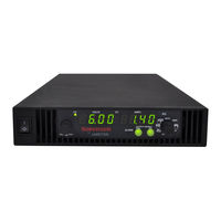
Ametek Sorensen XG 100-8.5 Operating Manual (282 pages)
850 Watt Programmable DC Power Supply
Brand:
Ametek
| Category:
Power Supply
| Size: 1 MB
Table of Contents
About this Manual
5
Conventions Used
5
Related Information
6
Font Conventions
6
Important Safety Instructions
7
Table of Contents
9
Introduction
21
Features and Options
22
XG 850 Watt Models (Firmware V1.11 and Higher)
23
Table 1-1 XG 850 Watt Series Voltage and Current Ranges
23
Front Panel
24
Figure 1-1 XG 850 Watt Front Panel
24
Front Panel Display and Controls
25
Figure 1-2 Front Panel Display and Controls
25
Rear Panel Connectors
26
Figure 1-3 Rear Panel: 6 V to 40 V Models
26
Figure 1-4 Rear Panel: 60 V to 150 V Models
26
Figure 1-5 Rear Panel: 300 V to 600 V Models
26
Installation
29
Basic Setup Procedure
30
Table 2-1 Basic Setup Procedure
30
Step 1: Inspecting and Cleaning
31
Initial Inspection
31
Periodic Cleaning
31
Step 2: Location and Mounting
32
Rack Mounting
32
Purchasing Rack Mount Kits
32
Ventilation
32
Step 3: Connecting AC Input Power
33
AC Input Connector
33
Step 4: Selecting Load Wires
34
Load Wiring
34
Table 2-2 Current Carrying Capacity for Load Wiring
34
Figure 2-1 Maximum Load Wire Length for 1 V Line Drop
35
Step 5: Performing Functional Tests
36
Powering the Power Supply On/Off
36
Voltage and Current Mode Operation Checks
37
Step 6: Connecting Loads
38
DC Output Connectors
38
Inductive Loads and Batteries
39
Figure 2-2 Diode Placement
39
Connecting Single Loads
40
Connecting Multiple Loads
40
Figure 2-3 Connecting Single Loads
40
Step 7: Connecting Remote Sensing
41
Figure 2-4 Remote Sense Connection
41
Local Operation
43
Configuring Settings
43
Introduction
44
Configuring Settings from the Front Panel
44
Using the 9-Position Mode Control
44
Using the Rotary Adjust/Enter Control
44
Figure 3-1 9-Position Mode Control
44
Coarse and Fine Adjustment Modes
45
Table 3-1 Select and Set from the Front Panel
45
Navigating the Menu System
47
Setting VOLTS and AMPS Modes
47
Normal Display Mode and Inactivity Timeout
49
Figure 3-2 Front Panel
49
Figure 3-3 Front Panel Menu System
50
Display Messages on the Front Panel
51
Table 3-2 Front Panel Display Text
51
Standard Operation
54
Operating Modes
54
Constant Voltage Mode Operation
55
Constant Current Mode Operation
55
Automatic Mode Crossover
55
Figure 3-4 Operating Modes
56
Shipped Configuration (Local Operation)
58
Enabling the Output
58
Table 3-3 Shipped Configuration
58
Enabling the Auxiliary Output
59
Output Auto Start Mode (Auto Restart)
59
Auxiliary Auto Start Mode
60
Alarms and Errors
61
Table 3-4 Alarm Order of Precedence
61
Clearing Alarms
62
Front Panel ALARM LED
63
Alarm Masking
64
Table 3-5 Alarm Mask Bit Positions
64
Alarm Output Latching
65
Table 3-6 Alarm Latch Bit Positions
65
Setting Foldback Mode
66
Resetting Activated Foldback Protection
67
Using over Voltage Protection (OVP)
68
Defining the OVP Set Point
69
Using under Voltage Protection (UVP)
70
Defining the UVP Set Point
71
Over Current Protection (OCP)
71
Using over Temperature Protection Lock (OTP)
72
Defining the OTP Mode
72
Resetting in Latch Mode
72
Using the External Shutdown Function
73
Activating the External Shutdown Function
73
Controlling the External Shutdown Function
73
Defining the Polarity of the External Shutdown Signal
74
Interlock Function
75
Defining the Interlock Mode
75
Output Protection
75
Programming Voltage Output Preset
75
Programming Current Output Preset
76
Power on Status Signal
77
Hardware Malfunction Alarms
77
Current Configuration Memory Settings
78
Table 3-7 Power Cycle Saved/Recalled Settings
78
User Setting Memory Locations
79
Saving User Setting Memory Locations
79
Table 3-8 User Accessible Saved/Recalled Settings
79
Recalling User Setting Memory Locations
80
Local Lockout
81
Enabling Local Lockout
81
Disabling Local Lockout
81
Resetting the Power Supply
82
Table 3-9 Power Supply Default Settings
82
Using Multiple Power Supplies
84
Figure 3-5 Split Supply Operation
85
Configuring Multiple Supplies for Series Operation
86
Figure 3-6 Series Operation
86
Figure 3-7 Load Connections in Remote Sensing Mode
87
Configuring Multiple Supplies for Current Sharing Operation (APG Method)
88
Setting Foldback Protection
90
Connecting to the Load in Local Sensing Mode (Parallel Control Method)
91
Figure 3-8 Load Connections in Local Sensing Mode
91
Connecting to the Load in Remote Sensing Mode (Parallel Control Method)
92
Figure 3-9 Load Connections in Remote Sensing Mode (Parallel Control Method)
92
Analog Programming (APG) and Isolated Analog Programming (ISOL)
93
Introduction
94
Analog Programming (APG) of Output Voltage and Output Current
94
Remote Programming Options
95
Analog Monitor Signals
95
Table 4-1 Monitor Lines
95
Auxiliary Outputs
96
Table 4-2 Remote Programming Options
96
Analog Programming (APG) Connector J1
97
Figure 4-1 APG Connector Terminals
97
Table 4-3 APG Pins and Functions J1
97
Making Control Connections
99
Figure 4-2 Inserting Screwdriver into Spring Terminal Block
99
Figure 4-3 APG and DC Output Connector
99
Analog Programming Mode
101
Analog Programming with External Voltage Source
101
Figure 4-4 Programming Output Voltage Using an External Voltage Source
101
Figure 4-5 Programming Output Current Using an External Voltage Source
101
Voltage-Controlled Voltage APG Setup
102
Activating APG Voltage Mode
102
Deactivating APG Voltage Mode
102
Query for Analog Voltage Input Level
103
Voltage-Controlled Current APG Setup
104
Activating APG Current Mode
104
Deactivating APG Current Mode
104
Query for Analog Current Input Level
105
Analog Programming with External Resistor
106
Figure 4-6 Programming Output Voltage Using an External Resistor
106
Figure 4-7 Programming Output Current Using an External Resistor
106
Resistive-Controlled Voltage APG Setup
107
Resistive-Controlled Current APG Setup
109
Voltage and Current Readback
111
Figure 4-8 Voltage Readback Using APG Connector J1
111
Figure 4-9 Current Readback Using APG Connector J1
111
Isolated Analog Programming Mode (ISOL)
112
AUX Output and Isolated Analog Programming (ISOL) Connector
112
Figure 4-10 aux Output and ISOL Connector Pinout
112
Table 4-4 aux Output and ISOL Connector Pins and Functions J3
113
Making ISOL Control Connections
115
ISOL Programming with External Voltage Source
115
Figure 4-11 Programming Output Voltage Using an Isolated External Voltage Source
115
Figure 4-12 Programming Output Current Using an Isolated External Voltage Source
115
Voltage-Controlled Voltage ISOL Setup
116
Activating ISOL Programming Voltage Mode
116
Deactivating ISOL Voltage Mode
116
Query for ISOL Voltage Input Level
117
Voltage-Controlled Current ISOL Setup
118
Activating ISOL Programming Current Mode
118
Deactivating ISOL Current Mode
118
Query for ISOL Current Input Level
119
Figure 4-13 Programming Output Voltage Using an Isolated External Resistor
120
Figure 4-14 Programming Output Current Using an Isolated External Resistor
120
Resistive-Controlled Voltage ISOL Setup
121
Resistive-Controlled Current ISOL Setup
123
Activating ISOL Resistive-Controlled Current Setup
123
Voltage and Current Readback (Isolated)
125
Figure 4-15 Isolated Voltage Monitoring
125
Figure 4-16 Isolated Current Monitoring
125
Query Remote Control Source State
125
Remote Operation
127
Introduction
128
Hardware and Connection Setup
129
Configuring Remote Control Using
129
Figure 5-1 Remote Control Connectors
129
Table 5-1 Remote Control Connector Pins and Functions J4 and J6
129
Table 5-2 DB-9 Pinouts
130
Table 5-3 RJ-45 Pinouts
130
Figure 5-2 RS-232 Communication Cable with DB-9 Pinout
131
Figure 5-3 DB-25 Pinout
131
Table 5-4 DB-25 Pinouts
131
Figure 5-4 RS-232 Communication Cable with DB-25 Pinout
132
Completing the Setup
132
Configuring Remote Control Using
133
Table 5-5 DB-9 Pinouts
133
Table 5-6 RJ-45 Plug Pinouts
133
Figure 5-6 RS-485 Communication Cable from Master to Slave Unit
134
Table 5-7 RJ-45 Plug on Slave Unit
134
Configuring Remote Control Using the USB Connector
135
Setting up the PC to Use the USB Connection
135
Figure 5-7 Found New Hardware Wizard
136
Figure 5-8 Install Hardware Device Drivers
136
Figure 5-9 Completing the New Hardware Wizard
137
Verifying Installation
137
Figure 5-10 Device Manager
138
Figure 5-11 Communications Port (COM1) Properties
139
Figure 5-12 Completing the New Hardware Wizard
139
Complete the Setup
140
Ethernet (ENET) or GPIB Connector (Optional)
141
Multiple Power Supply Connections to RS-485 Bus
141
Figure 5-13 Multi Power Supply Connection to RS-485 Bus
141
Multiple Power Supply Setup
142
Terminal Configuration
143
Data Format
143
End of Message
143
Hyperterminal
143
Figure 5-14 USB Settings
144
Figure 5-15 ASCII Setup
145
Selecting the Appropriate Communication Port
146
Data Rate Setting (Kbps)
146
Multichannel Address Setting
147
Remote Interface Addressing
148
Multichannel Commands Explained
149
Table 5-8 Rules for Multichannel Responses
149
Status Reporting in SCPI
151
Figure 5-16 SCPI Status Reporting Model
152
Status Registers Model from IEEE 488.2
153
Figure 5-17 IEEE 488.2 Register Model
153
Status Byte
154
Error/Event Queue (ERR)
154
Questionable Status Register Summary (QSR)
154
Table 5-9 Status Byte Summary Register
154
Message Available (MAV)
155
Standard Event Status Summary (ESB)
155
Master Summary Status (MSS)
155
Request Service (RQS)
155
Operation Status Register Summary (OSR)
156
Service Request Enable Register
156
Query the Status Byte
156
Standard Event Status Register (SESR)
157
Standard Event Status Enable Register
157
Figure 5-18 Summary of Standard Event Status Register
158
Table 5-10 Standard Event Status Register
158
Operation Complete
159
Wait-To-Continue Command
159
Standard SCPI Register Structure
160
Figure 5-19 SCPI Register Model
160
Operation Status Register
161
Figure 5-20 Operation Status Register Fanout
161
Table 5-11 Operation Status Register
162
Table 5-12 Operation Shutdown Status Register
163
Table 5-13 Operation Shutdown Protection Status Register
163
Current Share Sub-Register
164
Table 5-14 Operation Cshare Status Register
164
Operation Status Register Commands
165
Current Sharing Sub-Register Commands
166
Shutdown Sub-Register Commands
167
Query Shutdown Condition
167
Protection Sub-Register Commands
168
Query Protection Condition
168
Questionable Status Register
169
Figure 5-21 SCPI Questionable Registers Fanout
170
Table 5-15 Questionable Status Register
171
Voltage Sub-Register
172
Temperature Sub-Register
172
Table 5-16 Questionable Voltage Status Register
172
Table 5-17 Questionable Temperature Status Register
172
Questionable Status Register Commands
173
Voltage Status Register Commands
174
Temperature Status Register Commands
175
SCPI Error/Event Queue
176
Querying for the Errors
176
Querying for the Error Code Only
177
Querying for the Number of Errors in the Queue
177
Reset Command
178
Clear All Status Registers
179
Clear Status Command
179
SCPI Preset Status
180
Table 5-18 Preset Values of User Configurable Registers
180
Command Line Help System
181
Querying Help for All Command Headers
181
Querying Help for Legacy Command Headers
183
Locking and Unlocking the Front Panel
185
Auto Sequence Programming
185
Setting Dwell Time
186
Storing an Auto Sequence Program
186
Saving an Auto Sequence Program to File
187
Readback and Troubleshooting an Auto Sequence Program
187
Reloading an Auto Sequence Program
188
Configure Other Protection Mechanisms
192
Foldback Protection
192
Over Temperature Protection
193
Interlock Enable/Disable
194
Save and Recall
195
Set Analog Programming Level
195
Set Remote Programming Interface
196
Protection Mask (Enable Alarms)
197
Table 5-19 Alarms Bit Mask
197
Calibration and Troubleshooting
199
Introduction
200
Main Voltage and Current Calibration Principle
201
Understanding the Problem
201
Figure 6-1 Offset (Intercept) Error and Gain (Slope) Error
201
Step 1: Gain Calibration
202
Step 2: Offset Calibration
202
Figure 6-2 Calibration: Step 1 Gain Calibration
202
Figure 6-3 Calibration: Step 2 Offset Calibration
202
Step 3: Recalibrate Gain
203
Figure 6-4 Calibration: Step 3 Recalibrate Gain
203
Calibrating the Output Voltage
204
Gain Calibration
204
Offset Calibration
204
Calibrating the Output Current
205
Gain Calibration
205
Offset Calibration
206
Over Voltage Protection Calibration
207
Non-Isolated Analog Programming Calibration
208
Non-Isolated Voltage Monitoring Calibration
208
Non-Isolated Current Monitoring Calibration
209
Non-Isolated Voltage Programming of Voltage Calibration
210
Non-Isolated Resistive Programming of Voltage Calibration
211
Non-Isolated Voltage Programming of Current Calibration
212
Non-Isolated Resistive Programming of Current Calibration
213
Calibration Procedure for Isolated Modes
214
Isolated Voltage Monitoring Calibration
214
Isolated Current Monitoring Calibration
215
Isolated Voltage Programming of Voltage Calibration
216
Isolated Resistive Programming of Voltage Calibration
217
Isolated Voltage Programming of Current Calibration
218
Isolated Resistive Programming of Current Calibration
219
Calibrating the Input Voltage APG Signal
220
Calibrating the Input Current APG Signal
221
Storing and Loading Calibration Parameters
223
Restore Factory Calibration
224
Restore Default Calibration
224
User Diagnostics
224
Emergency Shutdown
225
Unusual or Erratic Operation
225
Troubleshooting for Operators
226
Table 6-1 Troubleshooting
226
A SCPI Command Reference
227
SCPI Conformance Information
228
Codes and Standards
228
IEEE 488.2/SCPI Syntax and Style
228
SCPI Command Hierarchy
229
Using SCPI Commands
230
Using Minimum and Maximum
231
Using Queries
231
Terminating Characters
232
Common Commands
232
Parameter Types
233
SCPI Command Tree
234
SCPI Command Summary
240
Table A-1 IEEE 488.2 Commands
240
Table A-2 Readback Commands
242
Table A-3 SCPI Commands for Output Control
243
Table A-4 SCPI Commands for Calibration
244
Table A-5 SCPI Commands to Clear All Protection Mechanisms
247
Table A-6 SCPI Commands for Foldback Protection
247
Table A-7 SCPI Commands for Power
248
Table A-8 SCPI Commands for Triggering
248
Table A-9 System Commands
249
Table A-10 Status Commands
252
Table A-11 Protection Commands
260
Table A-12 Auto Sequence Commands
260
Error Messages
263
Command Error List
265
Table B-1 Command Error List
265
Execution Error List
266
Table B-2 Execution Error List
266
Device-Specific Error List
267
Table B-3 Device-Specific Error List
267
Query Error List
268
Table B-4 Query Error List
268
Electrical Specifications for XG 850 Watt
270
Table C-1 XG 850 Watt Electrical Specifications for 6 V to 600 V Models
270
AC Line Input Specifications for XG 850 Watt
271
Remote Operation
272
Table C-2 Remote Operation
272
Common Specifications for All Models
273
Figure C-1 XG 850 Watt Mechanical Dimensions: 6 to 40 V Models
275
Figure C-2 XG 850 Watt Mechanical Dimensions: 60 V to 600 V Models
276
Index
279
Advertisement
Related Products
Ametek Sorensen XG 12.5-120
Ametek Sorensen XG 12-140
Ametek Sorensen XG 100-15
Ametek Sorensen XG 100-17
Ametek Sorensen XG 150-10
Ametek Sorensen XG 150-11.2
Ametek Sorensen XG 12-70
Ametek Sorensen XG 150-5.6
Ametek Sorensen XG 8-100
Ametek Sorensen XG 600-2.6
Ametek Categories
Measuring Instruments
Test Equipment
Power Supply
Switch
Controller
More Ametek Manuals
Login
Sign In
OR
Sign in with Facebook
Sign in with Google
Upload manual
Upload from disk
Upload from URL