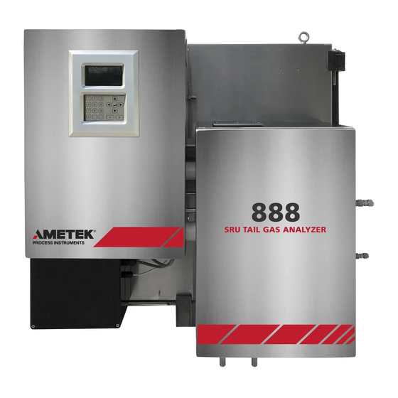
Sign In
Upload
Manuals
Brands
Ametek Manuals
Measuring Instruments
888
Ametek 888 Sulfur Recovery Analyzer Manuals
Manuals and User Guides for Ametek 888 Sulfur Recovery Analyzer. We have
2
Ametek 888 Sulfur Recovery Analyzer manuals available for free PDF download: User Manual
Ametek 888 User Manual (136 pages)
ATEX/IECEx tail gas analyzer
Brand:
Ametek
| Category:
Measuring Instruments
| Size: 14.47 MB
Table of Contents
Table of Contents
3
About this Document
7
Safety Notes
7
Important Safety Information
8
Warning Labels
10
Protective Conductor Terminal
10
Environmental Information (WEEE)
10
Electromagnetic Compatibility (EMC)
11
Classified, Hazardous Area Protection
12
Components and Functions
12
Warranty and Claims
14
CHAPTER 1 Overview
15
Model 888 Tail Gas Analyzer
15
Electronics Enclosure
16
Photometer
16
Xenon Lamp Assembly
17
Detector Assembly
17
Lamp & Detector Mounting
18
User Interface/Host Display
18
Sensor Board
18
Sample Conditioning (Oven) Enclosure
18
Light Tube/Mirror Block Assembly
20
Demister
21
Sample Cell
21
Steam Blowback Valve
22
Heat Exchangers
22
Customer Connections
23
Customer Drawing Package
25
Operation
26
Timing Sequence
26
CHAPTER 2 Specifications
29
Model 888 Tail Gas Analyzer
29
CHAPTER 3 Installation and Start-Up Prior to Installation
33
Analyzer Site Preparation
34
Unpacking and Inspection
34
Space Requirements
34
Installation Guidelines
37
Sample Tap Preparation
38
Installation Procedure
40
Installing the Probe
41
Installing the Demister
45
Purge Installation
47
Electrical Connections
48
System Start-Up and Operation
50
Leak Checking
50
Leak Checking (Without Power)
50
Purging the Electronic Enclosure
51
Adjusting the Purge Controller
52
System Operation
53
Analyzer Security - Passwords
53
Starting Normal Operation
54
Setting the Sample Gas Flow
55
Analyzer Timing
57
Normal Timing Sequence
59
Calibration Span Adjustment
61
Calibration Procedure
62
Analyzer Troubleshooting and Maintenance
65
Cleaning/Replacing Parts in the Sampling System
65
Other Maintenance
66
Sample System Leakage Test
66
Installation and Start-Up
33
Prior to Installation
33
Personnel Technical Level Required for Installation
33
CHAPTER 4 Controller / User Interface
69
Refer to 883056904 User Interface Manual for Details on the Amevision Interface
69
CHAPTER 5 Alarms
71
Alarm Relays
71
System Alarm - Relay 1
71
Data Valid Alarm - Relay 2
71
Programmable Relays - Relay 3 and Relay 4
71
Alarm Conditions and Responses
72
CHAPTER 6 Troubleshooting
75
Diagnostic Functions
75
Diagnostics Mode
75
Problems and Possible Causes
76
Oven/Cell Temperature Not Reaching Setpoint
76
Demister Temperature Not Reaching Setpoint
76
Low Light Conditions
77
Cleaning the Optical Surface
78
Check the Optical Alignment
79
APPENDIX A Wiring Diagrams
81
S and so 2 Calculations
81
CHAPTER 7 Parts Replacement
81
APPENDIX B H S and so Calculations
111
Concentration Measurement
111
Absorbance Calculation
111
Excess H
112
Air Demand
113
APPENDIX C Analyzer Timing
115
Timing States / Periods
115
Period 1 - Special Flush
115
Period 2 - Flush and Zero
115
Period 3 - Sample Flush
116
Period 4 - Measure
116
Zero and Photo-Span Calibration
116
Operation Sequences
117
Period 5 - Flush and Zero
117
Period 6 - Track Zero
117
Period 7- Photo-Span Calibration
117
Period 8 - Track Photo-Span Calibration
118
Steam Blowback
118
Period 9 - Pre-Steam Flush
118
Period 10 - Steam Blowback
118
Period 11 - Post Steam Flush
118
Special Periods
118
Period 12 - Continuous Flush
118
Period 13- Continuous Hold
119
Period 14 - Continuous Sample
119
APPENDIX D Parameter Ids / Modbus Addresses
121
Advertisement
Ametek 888 User Manual (122 pages)
Tail gas analyzer for Class I, Division 2 areas
Brand:
Ametek
| Category:
Measuring Instruments
| Size: 12.65 MB
Table of Contents
Table of Contents
3
Safety Notes
7
Grounding
7
Important Safety Information
8
Storage Information
9
Warning Labels
10
Special Warnings and Information
14
Warranty and Claims
15
CHAPTER 1 Overview
17
Model 888 Tail Gas Analyzer
17
Electronics Enclosure
18
Photometer
18
Xenon Lamp Assembly
19
Detector Assembly
19
Lamp & Detector Mounting
19
User Interface/Host Display
20
Sensor Board
20
Sample Conditioning (Oven) Enclosure
20
Flow Diagrams
21
Light Tube/Mirror Block Assembly
22
Demister
22
Sample Cell
22
Steam Blowback Valve
24
Heat Exchangers
24
Customer Connections Enclosure
25
Customer Drawing Package
26
Operation
26
Timing Sequence
26
Sample Flow
27
CHAPTER 2 Specifications
29
Model 888 Tail Gas Analyzer
29
CHAPTER 3 Installation and Start-Up
33
Prior to Installation
33
Analyzer Site Preparation
34
Unpacking and Inspection
34
Space Requirements
34
Installation Guidelines
36
Sample Tap Preparation
37
Installation Procedure
38
Installing the Probe
39
Installing the Demister
43
Electrical Connections
45
System Start-Up and Operation
47
Leak Checking
47
System Operation
48
Analyzer Security - Passwords
48
Starting Normal Operation
48
Setting the Sample Gas Flow
50
Analyzer Timing
52
Normal Timing Sequence
53
Calibration Span Adjustment
55
Calibration Procedure
55
Analyzer Troubleshooting and Maintenance
58
Sample System Leakage Test
60
CHAPTER 4 Controller / User Interface
61
CHAPTER 5 Alarms
63
Alarm Relays
63
Alarm Conditions and Responses
64
CHAPTER 6 Troubleshooting
67
Diagnostic Functions
67
Problems and Possible Causes
68
Oven/Cell Temperature Not Reaching Setpoint
68
Demister Temperature Not Reaching Setpoint
68
Low Light Conditions
69
Cleaning the Optical Surface
70
Check the Optical Alignment
70
CHAPTER 7 Parts Replacement
71
Part Numbers
72
APPENDIX A Wiring Diagrams
87
APPENDIX B H 2 S and so 2 Calculations
97
Concentration Measurement
97
Absorbance Calculation
97
APPENDIX B H S and so Calculations
101
APPENDIX C Analyzer Timing
101
Timing States / Periods
101
Period 1 - Special Flush
101
Period 2 - Flush and Zero
101
Period 3 - Sample Flush
102
Period 4 - Measure
102
Zero and Photo-Span Calibration
102
Operation Sequences
103
Period 5 - Flush and Zero
103
Period 6 - Track Zero
103
Period 7- Photo-Span Calibration
103
Period 8 - Track Photo-Span Calibration
104
Steam Blowback
104
Period 9 - Pre-Steam Flush
104
Period 10 - Steam Blowback
104
Period 11 - Post Steam Flush
104
Special Periods
105
Period 12 - Continuous Flush
105
Period 13- Continuous Hold
105
Period 14 - Continuous Sample
105
APPENDIX D Parameter Ids / Modbus Addresses
107
Advertisement
Related Products
Ametek Chandler Engineering 8040D10
Ametek Chandler Engineering 8340
Ametek Dunkermotoren 88740.01300
Ametek Dunkermotoren 88740.01270
Ametek 88720.01210
Ametek 88720.01220
Ametek dunkermotoren 88740.01230
Ametek dunkermotoren 88740.01260
Ametek 88740.01210
Ametek 88740.01220
Ametek Categories
Measuring Instruments
Test Equipment
Power Supply
Controller
Laboratory Equipment
More Ametek Manuals
Login
Sign In
OR
Sign in with Facebook
Sign in with Google
Upload manual
Upload from disk
Upload from URL