Sign In
Upload
Manuals
Brands
AMERITECH Manuals
Measuring Instruments
AM8a
AMERITECH AM8a Manuals
Manuals and User Guides for AMERITECH AM8a. We have
1
AMERITECH AM8a manual available for free PDF download: Instruction Manual
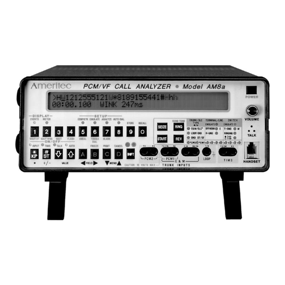
AMERITECH AM8a Instruction Manual (152 pages)
PCM/VF CALL ANALYZER
Brand:
AMERITECH
| Category:
Measuring Instruments
| Size: 0 MB
Table of Contents
February
2
Table of Contents
4
1 Front Panel Operation
18
Front Panel Programming Methods
18
Figure 1-1. Am8A Front Panel
18
Arrow Keys
19
Events and Meter Keys and Display
20
EVENTS ([SHIFT][1]) Key
20
Events Display Character Set
21
Figure 1-2. Am8A Events Display
21
Dialed Digits
22
METER ([SHIFT][2]) Key
24
Setup Area
25
CONFIG'N ([SHIFT][5]) Key
25
EMULATE ([SHIFT][6]) Key
25
ANALYZE ([SHIFT][7]) Key
25
AUTO DIAL ([SHIFT][8]) Key
25
Control On/Off Keys
26
INPUT ([SHIFT][*, KP]) Key
26
TIMS ([SHIFT][#, ST]) Key
26
Talk
27
Auto
27
Menu/Data Control Keys
27
FREEZE ([SHIFT][B]) Key
27
PRINT ([SHIFT][C]) Key
28
Cancel
28
Signaling Keys
28
SEIZE Key
28
START Key
29
RING Key
29
REV Key
29
SEND TONE ([SHIFT][RING]) Key
29
Data Entry Keys for Signaling
30
Wait Dt
30
Wait Wink
30
Wait
30
Flash
30
Unbalance
30
Toggle Dial
30
Blank
30
SIGNALING STATUS Leds
31
Figure 1-3. Signaling Status Leds
31
Store Setup
32
Recall Setups
33
RECALL Setup Parameters
33
RECALL Auto Dial Sequence
33
Speakerphone/Audio Monitor
33
Speakerphone in Talk Mode
33
Audio Monitoring
34
Handset
34
2 Configuration Parameters
36
Mode Config
36
Imitate
36
Mode
36
Circuit Config
37
Analog Impedance
37
Analog/Pcm
37
PCM CONFIG 1 and PCM CONFIG 2
38
Input
38
Zero Sup
38
Chan
38
OFF HK A/B or on HK A/B
40
Trunk Config
40
Trunk Type
41
Slc® Type
41
E & M Type
41
DISPLAY CONFIG 1 and CONFIG 2
42
Digit Detection
43
Slc Msg
43
SLC® Activity Message
44
T/T Mask (Single-Tone Event Selection)
44
Rs232 Config
44
Baud Rate
44
Parity
44
CR Delaysec
45
Security Config
45
Password
45
Setup Protect
45
Print Config
46
Off
46
All Calls,Events Only
46
All Calls,Events & Details
46
Flawed Calls,Events Only
46
Flawed Calls,Events & Details
46
Clock Config
47
Am8A CONFIG
47
3 Emulate Parameters
48
Loop Emulate
48
Voltage
48
Termination Emulate
48
DC Hold
48
Dialing Emulate
49
Loop Type
49
Start Signal
49
Pulse Emulate
49
Break
49
Intrdigitms
49
Dtmf/Mf Emulate 1
50
Hi:dbm/Hz
50
Lo:dbm/Hz
50
Dtmf/Mf Emulate 2
50
On/Offms
50
Send Tone Emulate
51
Dial Tone Emulate 2
51
T1:Dbm/Hz
52
T2:Dbm/Hz
52
DL Sndms
52
Recall Emulate
52
LINE Unbalms
52
Ringing Emulate 1
53
On/Offms
53
Ringing Emulate 2
53
Start Time Emulate
54
Dly:bgn/Endms
54
Wink:bgn/Durms
54
Sf Emulate
54
Freq+%Hz
54
4 Analysis Parameters
56
Hook Analyze
56
Flashms(Min)
56
Disconnectms(Min)
56
Strt Sig (Start Signal) Analyze: Expected Type
57
Dialtone/Wink
57
Dialtone/Delay
57
Dialtone
57
DT STRT (DIALTONE START) ANALYZE: DIALTONE Rcvdms (Min/Max)
57
Dly Strt (Delay Start) Analyze
58
STRT Bgnms(Min/Max)
58
Endms(Min)
58
Wink Strt
58
WINK Bgnms(Min)
58
Durms(Min/Max)
58
Pulse Analyze 1
59
Speedpps(Min/Max)
59
Break
59
Pulse Analyze 2
59
Interdigitms(Min)
59
Dtmf/Mf Analyze 1
60
LO Banddb(Min/Max)
60
HI Banddb
60
Dtmf/Mf Analyze 2
60
Freq%(Max)
60
Twistdb(Min/Max)
60
DTMF Frequencies
61
MF(R1) Frequencies
62
TONE On/Offms(Min)
63
Guardms
63
Threshold Analyze
63
Tonedbm(Min)
63
Dtmf/Mf Analyze 3
63
OFF Hkvdc(Min)
64
Procedure to Set off Hkvdc(Min) Threshold
64
5 Auto and Manual Dialing
66
Store Autodial Sequence
66
Select and Use Autodial Sequence
67
Manual Dialing
67
6 Meter Display
70
Measure/Scale Menu
70
Measure Display (Making Measurements)
70
Meter Selections and Connections
71
Figure 6-1. Cables for Am8A Front Panel Test/Meter Connections
72
Figure 6-2. Loop/Ground Start and DID Analog Test/Meter Front Panel Connections
73
Figure 6-3. E & M and SF Test/Meter Front Panel Connections
74
Figure 6-4. PCM T1/SLC®96 Test/Meter Front Panel Connections
75
Loop Start, Ground Start, DID - Analog Measure
76
T-R DC or Ac
76
CM DC or Ac
76
T-G DC or Ac
76
R-G DC or Ac
76
It(Ma) DC
76
E & M and SF - ANALOG MEASURE
78
TX Vt-R or RX Vt-R, DC or Ac
78
TX VCM or RX VCM, DC or Ac
78
Ve or VM, DC or Ac
78
Vsb or Vsg, DC or Ac
79
TX Tone or RX Tone
79
E & M and SF - ANALOG MEASURE
80
TX1 VCM or TX2 VCM, DC or Ac
80
RX1 VCM or RX2 VCM, DC or Ac
80
TX1 Tone or TX2 Tone
80
RX1 Tone or RX2 Tone
81
RX1 Dbdsx or RX2 Dbdsx
81
RX1 Dbdsx or RX2 Dbdsx in Emulation Mode
81
RX1 Dbdsx or RX2 Dbdsx in Monitor Mode
81
Noise Measure
81
PCM1 and PCM 2 BIPOLAR VIOLATION (COUNT and STATUS) MEASURE
82
Slips
83
Pcm 1 or Pcm 2 Frame Sync Measure
83
Ferr
83
T1 Time-Slot to Voice Channel Assignment
84
SLC®96 Mode I Time-Slot to Voice Channel Assignment
84
SLC®96 Mode II Time-Slot to Voice Channel Assignment
84
Figure 6-5. SLC®96 Mode 1 Channel Number to Time Slot Assignments
85
Slc®96 Mode I or II Messages
86
ALARM TX or RX
86
Figure 6-6. SLC®96 Alarm Conditions Meter Display
86
PROTECTION TX or RX
87
MAINTENANCE TX or RX
87
Figure 6-7. SLC®96 Alarm Conditions Meter Display
87
Figure 6-8. SLC®96 Alarm Conditions Meter Display
87
SLC®96 II Concentrator Field Messages
88
7 Rs232 Entries and Printouts
90
Rs232 Command Description
90
Printer Commands
91
Setup Menu Commands for CONFIG, EMULATE, and ANALYZE
91
Terminal Commands
91
AUTO DIAL Setup Commands
92
Display Menu
92
ON-OFF (Control Toggle) Commands
93
CALL INITIATE (Signaling) Commands
93
EVENTS DISPLAY Commands
93
METER DISPLAY Commands
93
Table 7-1. RS232 Terminal Commands
93
Table 7-2. RS232 Printing Commands
94
Table 7-3. RS232 Configuration Menu Commands
95
Table 7-4. RS232 EMULATE Menu Commands
98
Table 7-5. RS232 ANALYZE Menu Commands
99
Table 7-6. RS232 Auto Dial Setup Commands
101
Table 7-7. RS232 On-Off (Control Toggle) Commands
102
Table 7-8. RS232 Call Initiate (Signaling) Commands
102
Table 7-9. RS232 Events Display Commands
103
Table 7-10. RS232 Meter Display Commands (Analog Voltage Measurements)
103
Table 7-11. RS232 Meter Display Commands (Meter Selections)
103
Table 7-12. RS232 Meter Display Commands (PCM Measurements)
104
Printouts
105
Off
105
All Calls, Events Only
105
Figure 7-1. Event-Only Printout
105
Table 7-13. RS232 Meter Display Commands (Noise Measurements)
105
All Calls, Events & Details
106
Flawed Calls, Events Only
106
Flawed Calls, Events & Details
106
Figure 7-2. Events & Details Printout (Monitor Mode)
106
Manual Short Print
107
Figure 7-3. Events & Details Printout (Emulate Mode)
107
Figure 7-4. Manual Short Print (Meter Display Example)
107
Manual Long Print
108
Figure 7-5. Manual Short Print (EMULATE Analog Switch, Te, PCM Examples)
108
Figure 7-6. Manual Long Print (Meter Display Example)
109
Figure 7-7. Manual Long Print (Setup Example)
110
Rs232 Rear-Panel Connections
111
Printer Cable (48-0084) Connection
111
Chaining Cable (48-0083) Connection
112
Chained Unit Addressing Command
112
Figure 7-8. Am8A Rear Panel Connections
113
Figure 7-9. RS232 Printer Cable
114
Figure 7-10. RS232 Chaining Cable
114
8 Am8A TECHNICAL SPECIFICATIONS
116
9 Warranty, Service, and Calibration
126
Return of Unit
127
A. Appendix A: Meter Display
128
A.1 PCM Operations and Data Flow
128
A.1.2 CIRCUIT CONFIG Menu Settings
133
A.1.3 PCM CONFIG 1 and CONFIG 2 Menu Settings
134
A.1.4 TRUNK CONFIG Menu Settings
136
A.2 PCM Connection Diagrams
137
Advertisement
Advertisement
Related Products
AMERITECH AM100
AMERITECH AM5
AMERITECH AM5e
AMERITECH AM 1933
AMERITECH AM 1930
AMERITECH Categories
Cordless Telephone
Security System
Transmitter
Measuring Instruments
Test Equipment
More AMERITECH Manuals
Login
Sign In
OR
Sign in with Facebook
Sign in with Google
Upload manual
Upload from disk
Upload from URL