Sign In
Upload
Manuals
Brands
ALTUS Manuals
Controller
NX3003
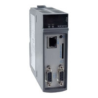
ALTUS NX3003 High-speed CPU Manuals
Manuals and User Guides for ALTUS NX3003 High-speed CPU. We have
2
ALTUS NX3003 High-speed CPU manuals available for free PDF download: User Manual
ALTUS NX3003 User Manual (221 pages)
Brand:
ALTUS
| Category:
Computer Hardware
| Size: 12 MB
Table of Contents
Table of Contents
3
Introduction
9
Nexto Series
9
Com
9
Innovative Features
10
Documents Related to this Manual
11
Visual Inspection
12
Technical Support
13
Warning Messages Used in this Manual
13
Technical Description
14
Panels and Connections
14
General Features
15
Common General Features
15
Memory
16
Protocols
18
Serial Interfaces
19
Com 1
19
Ethernet Interfaces
20
Net 1
20
Power Supply
20
Environmental Characteristics
21
Compatibility with Other Products
21
Performance
21
Application Times
22
Time for Instructions Execution
22
Initialization Times
22
Interval Time
22
Physical Dimensions
23
Purchase Data
24
Integrant Items
24
Product Code
24
Related Products
24
Installation
26
Mechanical Installation
26
Electrical Installation
26
Ethernet Network Connection
27
IP Address
27
Gratuitous ARP
27
Network Cable Installation
27
Serial Network Connection
28
Communication Without Termination
29
Communication with Internal Termination
30
Communication with External Termination
31
Communication Without Termination
31
Communication with Internal Termination
32
Communication with External Termination
33
Network Example
34
Architecture Installation
34
Module Installation on the Main Backplane Rack
34
Programmer Installation
34
Initial Programming
35
Memory Organization and Access
35
Project Profiles
37
Single
37
Basic
38
Normal
38
Expert
38
Custom
39
Machine Profile
39
General Table
40
Maximum Number of Tasks
41
CPU Configuration
41
Libraries
43
Inserting a Protocol Instance
43
Modbus Rtu
43
MODBUS Ethernet
44
Finding the Device
46
Login
48
Run Mode
50
Stop Mode
51
Writing and Forcing Variables
52
Logout
52
Project Upload
53
CPU Operating States
54
Run
54
Stop
54
Breakpoint
54
Exception
55
Reset Warm
55
Reset Cold
55
Reset Origin
55
Programs (Pous) and Global Variable Lists (Gvls)
55
Mainprg Program
55
Startprg Program
56
Userprg Program
56
GVL System_Diagnostics
56
GVL Disables
57
GVL Ioqualities
58
GVL Module_Diagnostics
59
GVL Reqdiagnostics
59
Prepare_Start Function
61
Prepare_Stop Function
61
Start_Done Function
61
Stop_Done Function
61
Configuration
62
CPU Configuration
62
General Parameters
62
Hot Swap
64
Hot Swap Disabled, for Declared Modules Only
64
Hot Swap Disabled
65
Hot Swap Disabled, Without Startup Consistency
65
Hot Swap Enabled, with Startup Consistency for Declared Modules Only
65
Hot Swap Enabled with Startup Consistency
65
Hot Swap Enabled Without Startup Consistency
65
How to Do the Hot Swap
66
Retain and Persistent Memory Areas
68
TCP Configurations
69
Project Parameters
71
External Event Configuration
71
Time Synchronization
72
Sntp
74
Daylight Saving Time (DST)
74
Serial Interfaces Configuration
74
Advanced Configurations
75
Ethernet Interfaces Configuration
76
Local Ethernet Interfaces
76
Net
76
Reserved TCP Ports
76
Protocols Configuration
77
Protocol Behavior X CPU State
79
MODBUS RTU Master
80
MODBUS Master Protocol Configuration by Symbolic Mapping
80
MODBUS Master Protocol General Parameters - Symbolic Mapping Configuration
80
Devices Configuration - Symbolic Mapping Configuration
83
Mappings Configuration - Symbolic Mapping Settings
84
Requests Configuration - Symbolic Mapping Settings
85
MODBUS Master Protocol Configuration for Direct Representation (%Q)
90
General Parameters of MODBUS Master Protocol - Setting by Direct Representation (%Q)
90
Devices Configuration - Configuration for Direct Representation (%Q)
91
Mappings Configuration - Configuration for Direct Representation (%Q)
92
MODBUS RTU Slave
94
MODBUS Slave Protocol Configuration Via Symbolic Mapping
94
MODBUS Slave Protocol General Parameters - Configuration Via Symbolic Mapping
95
Configuration of the Relations - Symbolic Mapping Setting
99
MODBUS Slave Protocol Configuration Via Direct Representation (%Q)
100
General Parameters of MODBUS Slave Protocol - Configuration Via Direct Representation (%Q)
100
Mappings Configuration - Configuration Via Direct Representation (%Q)
101
MODBUS Ethernet
103
MODBUS Ethernet Client
104
MODBUS Ethernet Client Configuration Via Symbolic Mapping
104
MODBUS Client Protocol General Parameters - Configuration Via Symbolic Mapping
105
Device Configuration - Configuration Via Symbolic Mapping
107
Mappings Configuration - Configuration Via Symbolic Mapping
108
Requests Configuration - Configuration Via Symbolic Mapping
110
MODBUS Ethernet Client Configuration Via Direct Representation (%Q)
114
General Parameters of MODBUS Protocol Client - Configuration for Direct Representation (%Q)
114
Device Configuration - Configuration Via Direct Representation (%Q)
115
Mapping Configuration - Configuration Via Direct Representation (%Q)
116
MODBUS Client Relation Start in Acyclic Form
119
MODBUS Ethernet Server
119
MODBUS Server Ethernet Protocol Configuration for Symbolic Mapping
119
MODBUS Server Protocol General Parameters - Configuration Via Symbolic Mapping
119
MODBUS Server Diagnostics - Configuration Via Symbolic Mapping
121
Mapping Configuration - Configuration Via Symbolic Mapping
123
MODBUS Server Ethernet Protocol Configuration Via Direct Representation (%Q)
124
General Parameters of MODBUS Server Protocol - Configuration Via Direct Representation (%Q)
124
Mapping Configuration - Configuration Via Direct Representation (%Q)
125
OPC da Server
127
Creating a Project for OPC da Communication
129
Configuring a PLC on the OPC da Server
132
Importing a Project Configuration
134
OPC da Communication Quality and Status Variables
134
OPC da Server Communication Limits
135
Accessing Data through an OPC da Client
136
OPC UA Server
138
Creating a Project for OPC UA Communication
139
Types of Supported Variables
140
Limit Connected Clients on the OPC UA Server
141
Limit of Communication Variables on the OPC UA Server
141
Encryption Settings
141
Main Communication Parameters Adjusted in an OPC UA Client
142
Endpoint URL
142
Publishing Interval (Ms) E Sampling Interval (Ms)
143
Lifetime Count E Keep-Alive Count
143
Queue Size E Discard Oldest
143
Filter Type E Deadband Type
143
Publishingenabled, Maxnotificationsperpublish E Priority
144
Accessing Data through an OPC UA Client
144
Ethernet/Ip
146
Ethernet/Ip Interface
146
Ethernet/Ip Scanner Configuration
148
General
148
Connections
149
Assemblies
151
Ethernet/Ip I/O Mapping
152
Ethernet/Ip Adapter Configuration
152
Module Types
152
Ethernet/Ip Module I/O Mapping
153
Communication Performance
153
MODBUS Server
153
Cpu's Local Interfaces
153
OPC da Server
154
OPC UA Server
155
System Performance
155
I/O Scan Time
156
RTC Clock
156
Function Blocks for RTC Reading and Writing
157
Function Blocks for RTC Reading
157
Getdateandtime
157
Gettimezone
158
Getdayofweek
159
Function Blocks and Functions of RTC Writing and Configuration
160
Setdateandtime
160
Settimezone
161
RTC Data Structures
162
Days_Of_Week
163
Timezonesettings
163
User Files Memory
164
Cpu's Informative and Configuration Menu
166
Function Blocks and Functions
168
Special Function Blocks for Serial Interfaces
168
Serial_Cfg
172
Serial_Get_Cfg
174
Serial_Get_Ctrl
175
Serial_Get_Rx_Queue_Status
177
Serial_Purge_Rx_Queue
178
Serial_Rx
178
Serial_Rx_Extended
182
Serial_Set_Ctrl
184
Serial_Tx
186
Inputs and Outputs Update
188
Refresh_Input
188
Refresh_Output
189
PID Function Block
190
Timer Retain
191
Tof_Ret
192
Ton_Ret
193
Tp_Ret
195
Snmp
195
Introduction
195
SNMP in Nexto Cpus
195
Private MIB
196
Configuration SNMP
196
User and SNMP Communities
198
User Management and Access Rights
199
Maintenance
200
Module Diagnostics
200
One Touch Diag
200
Diagnostics Via LED
200
DG (Diagnostic)
202
WD (Watchdog)
202
Diagnostics Via WEB
202
RJ45 Connector Leds
203
Diagnostic Explorer
205
Diagnostics Via Variables
205
Summarized Diagnostics
206
Detailed Diagnostics
209
Diagnostics Via Function Blocks
216
Gettaskinfo
216
Graphic Display
218
Not Loading the Application at Startup
219
System Log
220
Common Problems
220
Troubleshooting
221
Preventive Maintenance
221
Advertisement
ALTUS NX3003 User Manual (82 pages)
Brand:
ALTUS
| Category:
Controller
| Size: 7 MB
Table of Contents
Table of Contents
3
1 Introduction
7
Nexto Series Features
7
Module List
7
Cpus - Central Processing Units
7
Fieldbus Interfaces
7
Input Modules
7
Mixed I/O Modules
8
Output Modules
8
Power Supply Modules
8
Racks
8
Software
8
Special Modules
8
Accessories
9
Innovative Features
9
Architecture
10
Backplane Bus
10
Backplane Racks
10
Cpu
10
Power Supply Module (PSU)
10
Fieldbus Head
11
Fieldbus Interface
11
I/O Modules
11
Application Examples
12
Compact CPU
12
Single CPU
12
Single CPU with Remote Rack Expansion
13
Single CPU with Remote Rack Expansion and Loopback
14
Single CPU with Redundant Rack Expansion and Loopback
15
Fieldbus Interfaces
16
Fieldbus Interfaces with Redundancy
17
MODBUS TCP Head
18
CPU Redundancy
19
Minimum Configuration of a Redundant PLC (Without PX2612 Panel Usage)
19
CPU & Network Interface Modules Redundancy
20
Main Features
20
Cpus
20
High-Speed Backplane Bus
20
Modules
20
Capacities
21
CPU Programming & Firmware Update
21
Enhanced Diagnostics
21
High Availability
21
Hot-Swapping
21
Robustness
21
Terminal Block Insertion & Removal
21
MT8500 - Mastertool IEC XE
22
IEC 61131-3 Programming Languages
22
Editors for Project Configuration and Hardware Configuration
23
Object-Oriented Programming
23
Online, Debugging and Commissioning Features
23
Simulation
24
Web
24
User Documentation & Help Files
25
Docking View
26
Enhanced Diagnostics
26
I/O System
26
Environmental Conditions
26
Standards and Certifications
27
Documents Related to this Manual
28
Visual Inspection
29
Technical Support
30
Warning Messages Used in this Manual
30
2 Configuration
31
Configuration Steps
31
Step 1 - Determine Necessary I/O Modules
31
Step 2 - Determine Necessary Special Modules and Network Interfaces
31
Step 3 - Determine CPU
31
Step 4 - Determine Backplane Rack Quantity
32
Step 5 - Determine the Backplane Rack Connector Cover Quantity
32
Step 6 - Determine the Power Supply Module Quantity
32
Step 7 - Bus Expansion Modules and Bus Expansion Cables
32
Step 8 - External Power Supply
32
Step 9 - Mastertool IEC XE License Choice
32
Mastertool IEC XE Graphic Editor
33
Compatible Components Tree
33
Module Documentation Access
33
Architecture Verification
33
Bill of Materials
33
Configuration and Consumption
33
3 Panel Design
34
Mechanic Design
34
Dimensions
34
MM Nexto I/O Module
34
MM Nexto Jet I/O Module
35
MM Nexto I/O Module
36
CPU, Fieldbus Interfaces, Power Sources and Special Modules
37
2-Slot Base for Panel Assembly
38
Slot Backplane Rack (Without Hot Swap)
38
Slot Backplane Rack
39
16-Slot Backplane Rack
40
Assembled Module Depth in the Backplane Rack
40
Spacing between Modules and Other Equipment in the Panel
41
Chute Dimensioning
42
Horizontal/ Vertical Assembly
42
Thermal Design
42
Heat Dissipation in an Electrical Panel
42
Electrical Design
45
General Information
45
Panel Supply
45
Panel Cables Distribution
45
Panel Illumination
46
Grounding
46
Electromagnetic Interference
46
Shield
46
Noise Suppressors
46
Circuit with Diode
46
Circuit with Diode and Zener
47
Circuit with Varistor
47
RC Circuit
47
Circuit with Capacitor
48
Supply Distribution Outside the Panel
48
Lightning Protection
49
4 Installation
50
Visual Inspection
50
Mechanical Installation
50
Backplane Rack Fixation
50
Drilling
50
Assembly
51
Removal
53
Module Insertion
53
Modules Removal
55
I/O Modules
56
Frontal Cover
57
I/O Connector Insertion for Nexto and Nexto Jet Modules
58
I/O Connector Block Removal for Nexto and Nexto Jet Modules
61
I/O Connector Block
64
I/O Module Labels
64
Identification
64
Identification Number and Description
64
Installation Diagram
65
Label Insertion and Removal
67
Rack Connector Cover
69
Rack Connector Cover Insertion
69
Rack Connector Cover Removal
70
Electric Installation
71
Spring-Connectors
71
Cable Insertion
73
10-Pin Connector Block - NX9402
74
12-Pin Connector Block with Fixation - NX9405
74
18-Pin Connector Block with Fixation - NX9406
74
20-Pin Connector Block - NX9403
74
6-Pin Connector Block - NX9401
74
6-Pin Connector Block with Fixation - NX9404
74
Cable Assembly
75
Cable Fixation and Identification
75
Nexto Solution
75
Nexto Jet Solution
76
Cable Removal
77
Connections
78
Power Supply
78
Fuses
78
5 Maintenance
79
Module Diagnostics
79
One Touch Diag (OTD)
79
Diagnostics Mode Access
79
I/O Points Access
81
Module and I/O Points Description Access
81
Short Press and Long Press
82
Preventive Maintenance
82
Advertisement
Related Products
ALTUS NX5101
ALTUS NX5110
ALTUS NX5210
ALTUS NX6000
ALTUS NX6010
ALTUS NX6020
ALTUS NX9000
ALTUS NX9002
ALTUS NX9003
ALTUS NX9100
ALTUS Categories
Refrigerator
Controller
TV
Dryer
Computer Hardware
More ALTUS Manuals
Login
Sign In
OR
Sign in with Facebook
Sign in with Google
Upload manual
Upload from disk
Upload from URL