Sign In
Upload
Manuals
Brands
Altendorf Manuals
Saw
ElmoDrive F45
Altendorf ElmoDrive F45 Manuals
Manuals and User Guides for Altendorf ElmoDrive F45. We have
1
Altendorf ElmoDrive F45 manual available for free PDF download: Operating Manual
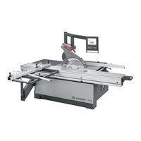
Altendorf ElmoDrive F45 Operating Manual (266 pages)
Brand:
Altendorf
| Category:
Saw
| Size: 13.83 MB
Table of Contents
Table of Contents
2
Foreword
5
Meaning of the Stated Descriptions
6
Machine Identification
6
Certificates
7
EC Prototype Testing Certificate
8
DGUV Test Certificate
12
Marks of Conformity
15
3 Product Description
16
Marking, Pictographs
16
Intended Use
16
Tools
17
Usable Saw Blades
18
Site of Installation/Use
18
Coolant Spray Device
18
Clamping Device
18
Machine Operator Positions
19
Foreseeable Misuse
20
Residual Risk
21
Dimensions and Weights
22
Auxiliary Power/Power Requirements
23
Emissions
25
Noise - Characteristic Values
25
Dust
27
Electromagnetic Compatibility
27
Ambient Conditions
28
Transport and Storage
28
Safety Information
29
Operational Safety
29
Deflector Wedge
31
Safety Devices
32
Top Safety Hood/Riving Knife
33
Handling Batteries / Accumulators
34
Information on Battery Regulations
34
Measures for Damage Prevention
34
Description of Machine
36
Definitions 4.1 Description of Machine
36
Terms
38
Scoring
38
Scoring Blade
38
Grooves
38
Packaging
40
Degree of Dismantling
40
Intermediate Storage
40
5 Transport, Siting and Installation
40
Safety Measures before Use/Installation
41
Installation Site
41
Foundation Plan
41
Space Requirement
43
Fixing
44
Installation
45
Telescopic Tube for Swinging Arm
45
Assembly, Telescopic Tube Standard/Compact
45
Installing the Telescopic Tube, 4Th Axis
46
Plug-Type Connections
46
Swivelling Arm, 4Th Axis
46
Main Table Length Extension
47
Assembly of TPL 840
47
Installing the Main Table Length Extension
47
Top Expansion 1600/2000 with Base Support
48
Rip Fence
49
Assembly of TPV
49
Installing the Measuring Bar
49
Installing the Main Table Width Extension
49
Cross-Slide and Crosscut Fence
51
Installing the Cross-Slide
51
Cross-Slide Clamping Mechanism WA/WGA/CNC Crosscut Fence uno 90
52
Clamping Lever
52
Cross-Slide Clamping, CNC Crosscut Fence DUO 90/DUO Flex
53
Cross-Slide Clamping, CNC Crosscut Fence DUO
53
Crosscut Fence, 90° Only
54
Changing the 90° Crosscut Fence
54
Installing the 90° Crosscut Fence
54
Crosscut-Mitre Fence
55
Crosscut-Mitre Fence Operating Elements
55
Installing the WGA
56
Crosscut-Mitre Fence Left-Hand Side
57
Crosscut-Mitre Fence WGA_LD
58
Crosscut-Mitre Fence with Digital Angle and Length Measurement
58
Assembly of the Crosscut Fence
58
Operating Elements
59
Wga_Ld
59
Transport, Siting and Installation
60
CNC Crosscut Fence
61
Operating Elements, CNC Crosscut Fence uno 90
61
Extension Installation
62
Operating Elements, 4Th Axis DUO 90
64
Installing the 4Th Axis
66
Electrical Connection
67
Operating Elements, 4Th Axis DUO Flex
68
Installing the 4Th Axis DUO Flex
69
Sliding Table
71
Bottom Carriage Stop
71
Installing the Middle Carriage
71
Installing the Top Carriage
72
Back Stop
72
Central Fixing
73
Bracket on the Bottom Carriage
73
Position of E-Chain
74
Fastening the E-Chain
75
Switch Cabinet
75
Fastening the E-Chain / Cable
76
Mains Connection
77
Electrical Connection
77
Circuit Diagram
78
Connecting the Extraction System (Customer Side!)
80
Bottom Extraction Connection
80
Basic Machine Setting
82
Sub Rollers on the Sliding Table
82
Check the Sub-Rollers
82
Setting of the Sub-Rollers
82
Main Table
83
Checking the Main Table
83
Adjusting the Main Table
83
Swinging Arm
84
Swivelling Arm, Check
84
Crosscut Fence Setting
84
Cross-Slide Height
85
Checking the Cross-Slide Height
85
Adjusting the Cross-Slide Height
85
Setting Free Cut
86
Setting: Manually Adjustable Rip Fence
87
Setting: Electromotive Rip Fence
87
Free Cut Setting, Electromotive PA
87
Angle Cut
88
Checking the Angle Cut
88
Factory Setting
88
0° Setting of the Saw Blade
89
Cutting a Test Piece
89
Checking the 0° -Setting
89
Working Safely with the Dimension Saw
90
Cross-Slide/Crosscut Fence
90
Cutting Solid Wood
90
Operating 6.1 Working Safely with the Dimension Saw
90
Function Description of the Crosscut-Mitre Fence
91
Adjusting the Angle
91
Position of Clamping Screws
91
Length Compensation
92
Length Compensation Scale
92
Stop Fences
93
Position of the Clamping Screw
93
Upright Position of the Stop Fence
93
Rip Fence
93
Flat Position of the Stop Fence
94
Double Roller Carriage
95
Sliding Table Operating Elements
95
Sliding Table Operating Elements, Manual
95
Sliding Table Operating Elements, TIP SERVO
95
Sliding Table Operating Elements, Vacuum Suction Cups
96
Working Examples
97
Rotational Speed
97
Position of the Hands
97
Edge Cutting (Trimming)
98
Tool: Circular Saw Blade for Longitudinal Cuts
98
Longitudinal Cutting of Narrow Workpieces
99
Longitudinal Cutting
99
Cutting Strips
99
Crosscutting Wide Workpieces
100
Tool: Circular Saw Blade for Crosscuts
100
Concealed Cutting, Rebating
101
Concealed Cutting, Grooves
101
Tool: Circular Saw Blade for Fine Cuts
101
Crosscutting against the Rip Fence
102
Crosscutting Short and Narrow Workpieces
103
Dividing Large Boards
104
Cutting with a Negative Cutting Angle
104
Machine Operation
105
Main Switch
105
Grey/Black Main Switch
105
Red/Yellow Main Switch
105
Switching the Saw Drives on and off
106
Switches for Saw Drives
106
Switches for Sliding Table Saw Drives
107
Setting the Speed
108
Changing the Rotational Speed
108
Fitting the Main Saw Blade
109
AKE Clamping System
109
Front Flange
109
Lock on the Middle Carriage
109
Fitting a Milling Tool
111
Adjusting the Riving Knife
112
Saw Blade Recommendation
113
Tbl. 6-1 Cutting Speed
113
Sliding Table Unlocked
114
Sliding Table Locked
114
Table Locking
114
Monitor Controls Elmodrive
115
Monitor Controls P-Terminal
115
ELMO II Start Screen
116
Start Screen / Tilting in both Directions
117
Start Screen
117
Start Screen / CNC Crosscut Fence DUO
118
Safety Area / Inching Mode
119
Description of Numeric Keypad Functions
119
Numeric Keypad
119
Calibration
120
Tool Management
121
Height Adjustment
122
Height Adjustment (Elmodrive)
122
Tilt Adjustment
123
Tilt Adjustment_Elmodrive, Tilting to One Side
123
Tilt Adjustment_Elmodrive, Tilting to both Sides
124
Motor Driven Rip Fence (Option)
127
Rip Fence Adjustment
127
Flat Guide Surface
128
High Guide Surface
128
Elmodrive Monitor with Man. Rip Fence
128
Infinitely Variable Speed Adjustment (Option)
129
Selecting the Rotational Speed for the Main Saw Blade
129
Set/Change Speed
130
Selecting a Stored Speed
131
Storing a Rotational Speed
132
Crosscut Fences
133
Manual Crosscut Fence
133
Screen Displayed for Tilt Angle 0°
133
Correction Dimension
136
CNC Crosscut Fence uno 90
137
CNC Crosscut Fence uno
137
CNC Crosscut Fence DUO 90
138
Setting the Dimension for the Throw-Over Stops
139
CNC Crosscut-Mitre Fence DUO FLEX
141
Screen after Pressing the EXTRAS Field
142
Calibrating the Crosscut-Mitre Fence
143
2-Axis Scoring Unit
146
Scorer Menu Button
146
Axis Scoring Saw
146
3-Axis Scoring Unit
148
RAPIDO Plus
148
Scoring Saw Setting
148
Function of the Axis Position Buttons
149
Setting the Scoring Saw Blade
150
Loading the Reference with the Active Saw Blade of the Tool Management
150
Vacuum Clamping in the Sliding Table
151
Monitor for Vacuum Table
151
6.4.10 Menu
152
Applications
153
Groove_Display Cut...of...cuts
154
Grooves_After Last Cut
154
Incremental Dimensions
156
Angle Cut with Oversize
157
Shifter Cut
159
Workpiece Positioning
159
“False” Mitre Function
160
“False” Mitre with Axis Display
161
“False” Mitre
162
Programs Function
165
Changing or Creating Programs
167
Selecting a Program
167
Geometric Shapes
170
Geometric Shapes, Triangle
171
Axis Function Mapped in
171
Geometric Shapes, Trapezoid
172
Geometric Shapes, Pentagon
172
Vacuum Clamping in the Sliding Table (Vacuum Table)
173
Utilities
174
Optimisation/Cutting Lists Function
174
Optimisation / Cutting Points
174
Total Process Time
175
Tool Management Deactivated
176
Tool Management Activated
177
Creating/Changing a Tool
178
Entering Designation
179
Entering Diameter
179
Entering Saw Blade Thickness
180
Input of a Rotational Speed
180
Input of the Main Blade Width
181
Inquiry When the Tool Management Is Left
181
For Option 3-Axes Scorer RAPIDO-Plus
183
Storing the Scorer
183
Adjusting Dimensions Following a Tool Change
184
Screen after Calibration of the Cutting Height
184
Actual Diameter Confirmed
185
Actual Diameter Saved
185
Basic Settings
187
Language
187
Setting of MM/Inch
188
Technician Level
190
Protection Hood
191
Protection Hood Swung Away
191
Normal Working Position
192
Changing the Protection Hood Sections
193
Swivel out the Hood Section
193
Large Protection Hood with Wide Hood Section
193
Protection Hood, Machine Tilting to both Sides
194
Lateral Displacement, Protection Hood
194
Optional Modules
195
Scorer, Tilting to One Side
195
Saw Blades
195
Two-Part Scoring Blade
195
Fitting the Saw Blade
196
RAPIDO Scoring Tool
196
Adjusting a Two-Part Scoring Blade
197
Adjusting the Scoring Blade for the RAPIDO Scoring Tool
198
Release the Clamping Screw
198
Adjust the Spindle
198
Replacing the Scoring Blade for RAPIDO
199
Using the allen Wrench
199
RAPIDO Saw Blades
199
Using the Internal Torx Wrench
199
Red Table Strip (Standard)
201
Red Table Strip with Lighting (Optional)
201
Rapido - Plus
202
Replacing Saw Blades
202
Disassembled RAPIDO Plus
202
RAPIDO-Plus, Fitting the Saw Blade
203
Scorer, Tilting to both Sides
204
3-Axis Scorer
204
Duet Set
204
Mitre Fences
205
Single-Sided Mitre Fence
205
Double-Sided Mitre Fence DUPLEX
205
Dimension Display Unit DIGIT L
207
Operating the Display Electronics
207
Power Supply
208
Changing the Rechargeable Battery
208
Changing the Rechargeable Battery for DIGIT L , DIGIT LD
208
Battery Charger
208
Basic Setting / Calibration of the Display Unit
209
Switching the Display Unit from MM to Inches or Inches to MM
209
Digital Angle and Length Display DIGIT LD
210
Crosscut-Mitre Fence Display Unit WGA_LD
210
Rip Fence with DIGIT X Digital Dimension Display
215
Changing the Batteries
215
Remove the Housing with the Display Unit
216
Undo the Screws and Remove the Cover
216
Change the Batteries, Ensuring Correct Polarity
216
Basic Setting of the Display Unit
217
Operating the Digit X
217
Calibrating the Display Unit
217
Parallel Cutting Device
219
PALIN Parallel Cutting Device
219
PALIN D Parallel Cutting Device
219
Workpiece Hold-Down Device
223
Manual Quick-Action Clamp
223
Klemmfix
223
Electro-Pneumatic Hold-Down Device
225
Remote Control, Hold-Down Device
226
Pneumatic Hold-Down Device
227
Tbl. 6-3 Beam Length
227
Vacuum Fastening in the Sliding Table
229
Suction Cup Rows
229
Cross-Slide Width Extension
230
6.6.10 Additional Cross-Slide
231
6.6.11 LASER Cutting Line Display
232
Aligning the Laser Beam with the Cutting Line
233
Aligning the Laser
233
6.6.12 Coolant Spray Device
234
6.6.13 Tip-Servo-Drive
235
7 Cleaning/Care
236
Safety Measures
236
Maintenance/Cleaning by the User
237
Cleaning of the Sub-Rollers of the Sliding Table
239
Open the Swinging Arm Compartment
239
Clean the Roller
239
Clean the Roller from below
240
Spray Guides with Universal Oil
241
Lubrication, CNC Rip Fence
243
Quantity of Lubricant
243
Motor Driven Rip Fence (X Axis)
243
Time Interval
243
Lubricating Process
244
Lubricating Nipple, X Axis
244
Lubricating Nipple, Saw Unit
245
How to Proceed
245
Lubricating the Scorer
246
Lubricating Nipple (Arrow), Scorer
246
Choice of Lubricants
248
Maintenance/Cleaning by Qualified Persons
249
Checking the Winding Shield
249
8 Faults/Problems/Troubleshooting
250
Machine Diagnosis
250
Response by Function Group 1
250
Motor Overload Protection
251
Troubleshooting/Faults/Messages
252
Electronic Brake Module
257
9 Technical Data
258
Standard Equipment
258
Sliding Table Cutting Lengths
261
Special Equipment
262
Available Special Equipment
262
Main Saw Drive
262
10 Maintenance and Repairs
264
General
264
Customer Service Addresses
265
Advertisement
Advertisement
Related Products
Altendorf F45 ProDrive
Altendorf WA 6
Altendorf WA 80
Altendorf Categories
Saw
Automobile Accessories
More Altendorf Manuals
Login
Sign In
OR
Sign in with Facebook
Sign in with Google
Upload manual
Upload from disk
Upload from URL