Sign In
Upload
Manuals
Brands
Alstom Manuals
Measuring Instruments
CBWatch3
Alstom CBWatch3 Manuals
Manuals and User Guides for Alstom CBWatch3. We have
1
Alstom CBWatch3 manual available for free PDF download: User Manual
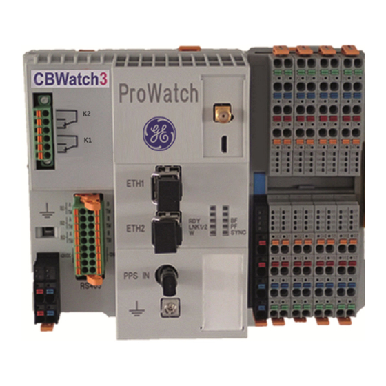
Alstom CBWatch3 User Manual (90 pages)
Circuit Breaker Monitoring
Brand:
Alstom
| Category:
Measuring Instruments
| Size: 9 MB
Table of Contents
Table of Contents
3
Index of Figures & Pictures
7
Purpose of this Document
10
Copyright
10
Safety Instructions and Warning
11
Handling Electronic Equipment
11
Unpacking
11
Storage
11
Set-Up
11
General Overview
12
Introduction
12
Product Description
12
Application
14
Optimisation of Corrective Actions Following a Failure
14
Implementation of Condition Based Maintenance
14
Technical Specifications
15
Description of Equipment
16
Power Supply
17
2-1.1 Description of Module
17
Potential Distributors
18
2-2.1 Description
18
Technical Data
18
Prowatch Module
19
2-3.1 Description of Module
19
2-3.2 Description of Leds
20
Description of Modbus RS485 Connector
21
Self-Test Functionality
21
2-3.5 K1 & K2 Programmable Output Contacts
22
DI16 Module
23
2-4.1 Description
23
2-4.2 Allocation of Terminals
24
2-4.3 Connections to Terminals
25
AI8 Module
26
2-5.1 Description
26
2-5.2 Allocation of Terminals
27
2-5.3 Connections to Terminals
28
RTD8 Module
29
2-6.1 Description
29
2-6.2 Allocation of Terminals
30
2-6.3 Connections to Terminals
30
DO16 Module
31
2-7.1 Description
31
Allocation of Terminals
32
2-7.3 Interface Relay
33
Common Indicators on Input/Output Modules
34
Description of Leds
34
Description of Sensors
35
SF 6 Gas Pressure and Temperature Sensor
35
3-1.1 Description
35
3-1.2 Technical Characteristics of the Sensor
35
Open/Close Command Detection Sensor Array
36
3-2.1 Description
36
DC Current Measurement Sensor
37
3-3.1 Description
37
3-3.1 Technical Characteristics of the Sensor
37
Control Circuit Continuity
38
3-4.1 Description
38
3-4.2 Connections
38
DC Voltage Measurement Sensor
39
3-5.1 Description
39
3-5.2 DC Converter Connections
39
3-5.1 DC Voltage Measurement - Connection Principle
40
Primary Current Measurement
41
Option 1 - Description
41
Option 1 - Connections
41
Option 1 - Connection Principle
41
3-6.4 Option 2 - Description
42
3-6.5 Option 2 - Converter Connections
43
3-6.6 Option 2 - Connection Principle
43
AC Current Measurement Sensor
44
3-7.1 Description
44
3-7.2 Technical Characteristics of the Sensor
44
AC Voltage Measurement Sensor
45
Description
45
3-8.2 Technical Characteristics of the Sensor
45
Pneumatic Pressure Sensor
46
Description
46
3-9.2 Technical Characteristics of the Sensor
46
Travel Sensor
47
3-10.1 Description
47
3-10.2 Technical Characteristics of the Sensor
47
Temperature Sensor
48
3-11.1 Description
48
3-11.2 Technical Characteristics of the Sensor
48
Human-Machine Interface (HMI)
49
TCP/IP Network Card Configuration
49
Connection to the Cbwatch3
52
Cbwatch3 Access Level
53
Cbwatch3 Network Connection
54
System Information
54
Description of the Monitoring Functions
55
SF 6 Gas Monitoring
56
5-1.1 General Description
56
5-1.2 Gas Measurements
56
5-1.3 Threshold Alarms
59
Long Term Trend Alarm before L1
60
Short Term Trend Alarm before L2
62
5-1.6 Liquefaction Alarm
62
5-1.7 Sensor Communication Error Counter
62
5-1.8 Alarm Summary
63
Control Circuit Monitoring
64
5-2.1 General Description
64
5-2.2 Presence of DC Supply
64
5-2.3 Continuity of Circuit
64
5-2.4 Coil Integrity
64
Alarm Summary
66
Operation Monitoring - Retrofit
67
5-3.1 General Description
67
5-3.2 Auxiliary Contacts Status
67
5-3.3 Number of Operations
67
5-3.4 Operating Times
68
5-3.5 Timing Alarms
69
5-3.6 Discordance between Poles
70
5-3.7 Timing Compensation
71
5-3.8 Operation Graphs
73
Operation Monitoring - New Build
75
5-4.1 General Description
75
Travel Sensor Kinematics
75
5-4.3 Contact Separation Speed
76
Bounces and the Final Position
77
Travel During a CO Cycle
78
Auxiliary Contact Switches
78
Arcing
80
Contact Wear Monitoring
80
5-5.1 General Description
80
5-5.2 Sampling of the Current before and During the Interruption
80
5-5.3 Cumulative Electrical Wear
81
5-5.4 Alarm Summary
82
Stored Energy Motor Monitoring
83
5-6.1 General Description
83
5-6.2 Motor Run Time
83
5-6.3 Motor Voltage
83
5-6.4 Motor Current
84
Spare Analogue Channels Monitoring
86
5-7.1 General Description
86
Temperature Monitoring
87
5-8.1 Ambient
87
5-8.2 Monitoring Heating of Cabinets
87
Monitoring
88
Alarms
88
5-9.1 Alarm Visualisation in HMI
88
5-9.2 Relay Alarms from Prowatch Module
88
Relay Alarms with Optional Alarm Modules DO16
88
Relay Alarms Assignment
88
Advertisement
Advertisement
Related Products
Alstom DS Agile C26 Series
Alstom DS Agile C264
Alstom iSTAT M212
Alstom iSTAT M232
Alstom iSTAT M2x2 Series
Alstom iSTAT M355
Alstom iSTAT M3x5 Series
Alstom M65B
Alstom M65D
Alstom M65EN
Alstom Categories
Relays
Circuit breakers
Measuring Instruments
Protection Device
Controller
More Alstom Manuals
Login
Sign In
OR
Sign in with Facebook
Sign in with Google
Upload manual
Upload from disk
Upload from URL