Sign In
Upload
Manuals
Brands
Alpego Manuals
Farm Equipment
K-DYNO
User Manuals: Alpego K-DYNO Subsoiler Rigid
Manuals and User Guides for Alpego K-DYNO Subsoiler Rigid. We have
1
Alpego K-DYNO Subsoiler Rigid manual available for free PDF download: Use And Maintenance Manual
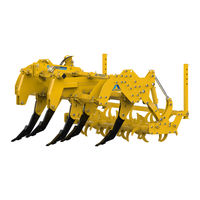
Alpego K-DYNO Use And Maintenance Manual (86 pages)
MECHANICAL SUBSOILERS
Brand:
Alpego
| Category:
Farm Equipment
| Size: 27 MB
Table of Contents
Table of Contents
3
Summary
3
List of Figures
6
List of Tables
7
General Information
8
Generalities
8
Copyrights
8
Use and Storage of the Manual
8
Symbols Used in this Manual
9
Terminology and Definitions
10
Numbering of Figures and Tables
10
Description of Personnel
10
User
10
Mechanical Repairer
11
Guarantees
11
Updating the Manual
12
Cooperation with the User
12
Manufacturer and Machine Data
13
Manufacturer and Machine Identification Data
13
Manufacturer's Name and Address
13
Instructions for Requesting Interventions
13
EC Declaration of Conformity
14
Machine Identification
15
Fig. 1 Marking Data
15
Machine Description
16
Intended Use
16
Reasonably Foreseeable Misuse
16
Technical Characteristics of the Machine
17
Technical Specifications Kdyno
17
Kevo Technical Specifications
17
Tab. 1 Complete Kdyno
17
Tab. 2 Complete Kevo
17
Kforce Technical Specifications
18
Noise
18
Tab. 3 Full Kforce
18
Machine Parts
19
Kdyno
19
Fig. 2 Parts Overview Kdyno
19
Tab. 4 Parts Description Kdyno
19
Kevo
20
Fig. 3 Overview of Parts Kevo
20
Tab. 5 Parts Description Kevo
20
Kforce
21
Fig. 4 Parts Overview Kforce
21
Tab. 6 Parts Description Kforce
21
Legal References and Responsibilities
22
Applied Directives and Technical Reference Standards
22
Risk Analysis
22
Manufacturer's Liability
23
Charges Borne by the Customer
23
General Safety Information
24
Residual Risks and Personal Protective Equipment
24
Tab. 7 Personal Protective Equipment
24
Ecology and Pollution
25
Safety and Accident Prevention Rules
26
Basic Warnings
26
Prohibitions
28
Fig. 5 Ban Points Ascent
29
Fig. 6 no Passing or Parking Points
30
Safety Devices
31
Mechanical Safety Devices
32
Calibrated Screws
32
Fig. 7 Safety Device (Normal Strain - Overload)
32
Tab. 8 Table Size and Class of Calibrated Screws
32
Safety Signage
33
Tab. 9 Safety Signs Applied to the Machine
34
Safety Warnings Displayed on the Machine
35
Fig. 8 Safety Warnings Applied to the Machine
35
Transport and Handling
36
General Warnings
36
Machine Reception
36
Machine Lifting
37
Lifting Machine in "Transport Set-Up
37
Fig. 9 Lifting Machine in "Transport Set-Up
37
Lifting a Mounted Machine
38
Fig. 10 Lifting a Mounted Machine
38
Accessory Lifting
39
Fig. 11 Accessory Lifting
39
Installation
40
Correct Weight Distribution
40
Fig. 12 Incorrect Weight Distribution
40
Fig. 13 Correct Weight Distribution
40
Counterweight Calculation
41
Fig. 14 Counterweight Calculation
41
Tab. 10 Counterweight Legend
41
Connection to the Tractor
42
Kdyno Connection Procedure
43
Fig. 15 Kdyno Connection Procedure
43
Kevo Connection Procedure
44
Fig. 16 Kevo Connection Procedure
44
Fig. 17 Categories Kevo Bindings
45
Kforce Connection Procedure
46
Fig. 18 Kforce Connection Procedure
46
Fig. 19 Categories Kforce Bindings
47
Hydraulic Connection
48
Fig. 20 Hydraulic Connection
48
Transit on Public Roads
49
Fig. 21 Transit on Public Roads
50
Operating Zones
51
Working Area
51
Normal Working Zones with Machine at Standstill
51
Fig. 22 Working Area
51
Fig. 23 Example of a 'Machine under Maintenance'sign
51
Fig. 24 Normal Working Zones with Machine at Standstill
52
Use
53
Fig. 25 Positioning Support Legs by Working Mode
53
Use of Side Containment Strips
54
Mechanical Bands in Working Position
54
Fig. 26 Positioning the Side Straps Accessory in the Working Position
54
Hydraulic Bands in Working Position
55
Fig. 27 Side Straps Accessory (Opening - Closing)
55
Bandanas in an Excluded Position
56
Fig. 28 Side Straps Accessory (Opening - Closing)
56
Generalities
57
Fig. 29 Correct Use
57
Fig. 30 Prohibited Use
58
User Function
59
Preliminary Checks
59
Use with Tractors Equipped with Draft Control on the Linkage
59
Use with Tractors Without Draft Control on the Linkage
59
Adjustment
60
Accessory Roller Working Angle Adjustment
61
Fig. 31 Accessory Roller Working Angle Adjustment
61
Adjusting the Working Height of Accessory Straps
62
Fig. 32 Accessory Roller Working Angle Adjustment
62
Mechanical Roller Depth Adjustment
63
Fig. 33 Mechanical Roller Depth Adjustment
63
Hydraulic Roller Depth Adjustment
64
Fig. 34 Hydraulic Roller Depth Adjustment
64
Maintenance
65
Generalities
65
General Information on Safety and Specific Risks
65
Routine Maintenance
66
Machine Cleaning and Residue Removal
66
Tab. 11 Ordinary Maintenance Schedule
66
Machine Control
67
Bearing Lubrication
68
Fig. 35 Media Lubrication
68
Pin Lubrication
69
Fig. 36 Pin Lubrication
69
Checking and Tightening, if Necessary, the Bolts of the Entire Machine
70
Checking the Readability of Pictograms
70
Tab. 12 Table of Recommended Tightening Torques for Hardware
70
Storage
71
Reset for Restart after Storage
71
Inconveniences, Causes and Remedies
72
Tab. 13 Troubleshooting
72
Disposal
73
Professional Profile of the Operator
73
General Information on Safety and Specific Risks
73
Materials
74
Sequence of Operations to Dismantle the Machine and Dispose of the Materials It Contains
74
Disconnecting the Hydraulic Supply
74
Tab. 14 Machine Materials
74
Disposal of the Structure
75
Recommended Spare Parts
75
How to Order Recommended Spare Parts
75
Recommended Spare Parts
76
Fig. 37 Recommended Spare Parts
76
Replacement of Kdyno Wear Parts
77
Fig. 38 Kdyno Protection Replacement
77
Fig. 39 Kdyno Ploughshare Replacement
77
Fig. 40 Replacement Kdyno Exploder
77
Replacement of Wear Parts Kevo - Kforce (ALFAST)
78
Fig. 41 Replacement of Kevo Protection - Kforce
78
Fig. 42 Replacement Ploughshare Kevo - Kforce
78
Fig. 43 Replacing the Kevo - Kforce Exploder
78
Accessories
79
Machine Accessories
79
Fig. 44 Accessory "Roller H12" on Kdyno
79
Fig. 45 M12 Roller" Accessory on Kdyno
80
Fig. 46 Accessory "Roller H22" on Kevo
81
Fig. 47 H50 Roller" Accessory on Kevo
82
Fig. 48 Containment Band Accessory
83
Fig. 49 Accessory Rear Lights with Reflector Triangles
84
Fig. 50 Exploder Accessory
85
Advertisement
Advertisement
Related Products
Alpego SKAT K1 Series
Alpego SKAT K1 5-250
Alpego SKAT K1 7-300
Alpego SKAT K1 9-400
Alpego SKAT K2 Series
Alpego SKAT K2 5-250
Alpego SKAT K2 7-300
Alpego SKAT K2 9-400
Alpego K-EVO
Alpego K-FORCE
Alpego Categories
Farm Equipment
Paper Shredder
Tiller
Spreader
Seeders
More Alpego Manuals
Login
Sign In
OR
Sign in with Facebook
Sign in with Google
Upload manual
Upload from disk
Upload from URL