Sign In
Upload
Manuals
Brands
Allweiler Manuals
Water Pump
NT Series
Allweiler NT Series Manuals
Manuals and User Guides for Allweiler NT Series. We have
1
Allweiler NT Series manual available for free PDF download: Original Operating Manual
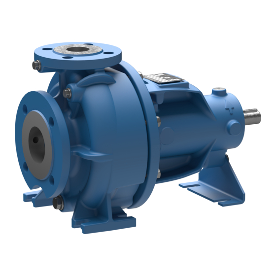
Allweiler NT Series Original Operating Manual (52 pages)
Centrifugal Pump with Volute Casing
Brand:
Allweiler
| Category:
Water Pump
| Size: 3 MB
Table of Contents
Table of Contents
2
About this Document
5
Target Groups
5
Other Applicable Documents
5
Target Groups and Their Duties
5
Other Applicable Documents and Their Purpose
5
Warnings and Symbols
6
Technical Terms
6
Warnings and Consequences of Disregarding Them
6
Symbols and Their Meaning
6
Technical Terms and Their Meaning
6
Safety
7
Intended Use
7
General Safety Instructions
7
Product Safety
7
Operator's Obligations
8
Obligations of Personnel
8
Specific Hazards
8
Explosion-Hazard Area
8
Electric Shock
9
Hazardous and Spraying (Pumped) Liquids
9
Moving Parts
9
Hot Surfaces
9
Layout and Function
10
Labels
10
Type Plate
10
Digital Nameplate
10
Fig. 1 Type Plate (Example)
10
(Example)
10
Transmitter (Example)
10
Pump Type Code
11
Fig. 4 Pump Type Code (Example)
11
Layout
12
Shaft Seals
12
Mechanical Seals
12
Stuffing Box
12
Fig. 5 NT Layout
12
Auxiliary Systems
13
Sealing Systems
13
(Sketch)
13
Tics
13
Transport, Storage and Disposal
14
Transport
14
Unpacking and Inspection on Delivery
14
Lifting
14
Fig. 7 Fastening Lifting Gear to Pump Unit
14
Fig. 8 Fastening the Lifting Gear to the Pump
14
Fig. 9 Setting down the Pump Without an Installed Support Foot
14
Fig. 14 Checking the Alignment of the Tab
14
Treatment for Storage
15
Storage
15
Removing Preservative
15
Disposal
15
Setup and Connection
16
Preparing the Setup
16
Checking the Ambient Conditions
16
Preparing the Installation Site
16
Preparing the Foundation and Surface
16
Removing Preservative
16
Installing the Heat Insulation (Optional)
16
Installation on a Foundation
17
Placing the Pump Unit on the Foundation
17
Fastening the Pump Unit
17
Fig. 10 Installation with Foundation
17
Fig. 11 Checking for Distortion
17
Installation Without a Foundation
18
Installing the Motor
18
Planning the Pipes
18
Specifying Supports and Flange Connections
18
Specifying Nominal Diameters
18
Fig. 12 Installation Without a Foundation
18
Specifying Pipe Lengths
19
Optimizing Changes in Cross-Section and Direction
19
Discharging Leaks
19
Providing Safety and Control Devices (Recommended)
19
Connecting the Pipes
19
Keeping the Piping Clean
19
Installing Auxiliary Pipes (if Available)
19
Installing the Suction Pipe
19
Fig. 13 Straight Pipe Lengths Upstream
19
Installing the Pressure Pipe
20
Inspection for Stress-Free Pipe Connections
20
Checking the Support Foot for Distortion (if Available)
20
Electrical Connection
20
Connecting the Motor
20
Checking the Sense of Rotation
20
Aligning the Coupling Precisely
21
Coupling
21
Fig. 15 Checking for Lateral and Vertical
21
Fig. 16 Checking for Angular Displacement
21
Aligning the Motor
22
Aligning the Motor with Sets of Shims
22
Aligning the Motor with Adjusting Screws
22
5.10 Installing the Coupling Guard
22
Screws
22
Operation
23
Preparations for the Initial Start-Up
23
Identifying the Pump Type
23
Removing Preservative
23
Lubricating the Bearings
23
Preparing Auxiliary Systems (if Available)
23
Filling and Bleeding
23
Start-Up
24
Switching on
24
Switching off
24
Shutting down the Pump
24
Measures to be Taken if the Pump Is Shut down
24
Measures Depending on the Behavior of the Pumped Liquid
24
Start-Up Following a Shutdown Period
25
Operating the Stand-By Pump
25
Measures to be Taken after Prolonged Shutdown Periods
25
Maintenance
26
Inspections
26
Antifriction Bearings Lubricated with
26
Grease
26
Mechanical Seals
26
Stuffing Box
26
Cleaning the Pump
26
Dismounting
27
Returning the Pump to the Manufacturer
27
Preparations for Dismounting
27
Measures for Return
27
Installing
28
Ordering Spare Parts
28
Troubleshooting
29
Malfunction/Number Assignment
29
Troubleshooting List
31
Appendix
32
Sectional Drawing
32
Auxiliary Connections
32
Part Numbers and Designations
32
Tab
32
Connection Designation Abbreviations
32
Designation of Components According to Part Numbers
33
Sectional Drawings
34
Fig. 18 U
34
Fig. 19 U3
35
Fig. 20 U3
36
Fig. 21 U3
37
Fig. 22 U3
38
Fig. 23 U3
39
Fig. 24 U3
40
Versions and Details at Bearing Bracket
40
Seals
41
Coupling Guard
41
Flushing
41
Fig. 26 U3
41
Seal
41
Fig. 28 U1B - Stuffing Box with Self-Locking
41
Fig. 29 Coupling Guard on Base Plate Versions
41
Technical Specifications
42
Ambient Conditions
42
Parameters for Auxiliary Systems
42
Sound Pressure Level
42
Tab. 19
42
Open Flow System
42
Tightening Torques
43
Cleaning Agents
43
Lubricants
43
Tab
43
Grease Types
43
Minimum Amounts for Grease Lubrication
43
Bearing Bracket Size
44
Height Offset for Motor Alignment with
45
Adjusting Screw
45
Tab
45
Height Setting at the Adjusting Screw
45
Flange Loads According to ISO 5199
46
Fig. 30 Empirical Formulas for Forces and
46
Fig. 31 Flange Loads at the Pump
46
Temperature
47
Flange Loads
47
Spare Parts for Two Years of Continuous Operation According to DIN 24296
48
Tab
48
Spare Parts for Two Years of Continuous Operation
48
Declaration of Harmlessness
49
Declaration of Conformity According to EC Machine Directive
50
Advertisement
Advertisement
Related Products
Allweiler NAM-F Series
Allweiler NIT Series
Allweiler NB Series
Allweiler AE E Series
Allweiler AE H Series
Allweiler AE N Series
Allweiler AE Series
Allweiler AE V Series
Allweiler AE.V Series
Allweiler AE1+1H Series
Allweiler Categories
Water Pump
More Allweiler Manuals
Login
Sign In
OR
Sign in with Facebook
Sign in with Google
Upload manual
Upload from disk
Upload from URL