Sign In
Upload
Manuals
Brands
Allied Vision Manuals
IP Camera
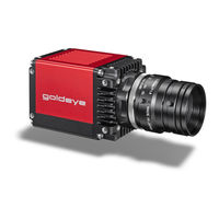
Goldeye CL Series
Allied Vision Goldeye CL Series Manuals
Manuals and User Guides for Allied Vision Goldeye CL Series. We have
2
Allied Vision Goldeye CL Series manuals available for free PDF download: Technical Manual
Allied Vision Goldeye CL Series Technical Manual (234 pages)
GIGE VISION & CAMERA LINK SWIR CAMERAS
Brand:
Allied Vision
| Category:
IP Camera
| Size: 14 MB
Table of Contents
Table of Contents
2
Goldeye G/CL at a Glance
8
Contents of Your Delivery
8
What else Do You Need
8
Contact Allied Vision
9
Website
9
Support and General Inquiries
9
Sales Offices
9
Headquarters
9
Document History and Conventions
10
Document History
11
Conventions Used in this Manual
14
Styles
14
Symbols and Notes
15
Compliance, Safety, and Intended Use
16
Compliance Notifications
17
For Customers in Europe
17
For Customers in the USA
17
Camera Applications and Intended Use
19
General Use
19
Use in Medical Devices
19
Copyright and Trademarks
20
Installation and Hardware Gige
21
Getting Started
22
Optics
22
Gige Vision Software
22
Overview of Installation
23
Mounting the Camera
24
Configuring the Host Computer
25
Installing the Ethernet Adapter Driver
25
Updating the Driver Manually
25
Modifying Ethernet Adapter IP Address
26
Optimizing the Ethernet Adapter
26
Jumbo Packets
27
Installing Viewer Software
28
Allied Vision Software
28
Vimba Viewer Documentation
28
Third-Party Software
28
Connecting Your Camera
30
Accessories
30
Camera Drivers
30
Powering up the Camera
30
Connecting to Host Application
31
Launch the Application
31
Acquiring Images
32
Troubleshooting
33
Questions and Answers
33
Is the Camera Getting Power
33
Additional References
33
Installation and Hardware CL
34
Getting Started
35
Optics
35
Frame Grabber
35
Cables
35
Allied Vision Software
36
Overview of Installation
36
Mounting the Camera
37
Powering up the Camera
37
Installing Hardware and Software
38
Installing a Frame Grabber
38
Installing Frame Grabber Software
38
Installing Camera Software
38
Installing Vimba Viewer on Windows
39
Starting the Camera
40
Powering up the Camera
40
Connecting to Host Computer
40
Camera Control and Image Viewing
41
Vimba with Frame Grabber Specific Viewer
41
Overview
41
Adjusting the Transfer Speed for Your Frame Grabber
41
Launch the Applications
42
Adjust Camera Controls: Controller Window
45
Grabbing Images
45
Camera Information: Information Window
46
Using a Custom Application
47
Using Frame Grabber Transport Layer
47
Troubleshooting
49
Questions and Answers
49
Is the Camera Getting Power
49
Is the Camera Powered, but Not Detected in Viewer
49
Is the Camera Listed in Viewer, but Images Cannot be Acquired
49
Additional References
50
Specifications
51
Technical Overview
52
Frame Rates and Temperature Control
52
Models and Modular Options
53
Shock and Vibration Testing Standards
53
Model Naming
53
Technical Specifications
56
Goldeye CL-008 SWIR TEC1
56
Goldeye CL-008 SWIR Cool TEC1
62
Goldeye CL-032 SWIR TEC1
67
Goldeye CL-032 SWIR Cool TEC2
72
Goldeye CL-033 SWIR TEC1
77
Goldeye CL-033 SWIR Tecless
83
Goldeye G-008 SWIR TEC1
89
Goldeye G-008 SWIR Cool TEC1
94
Goldeye G-032 SWIR TEC1
99
Goldeye G-032 SWIR Cool TEC2
104
Goldeye G-033 SWIR TEC1
109
Goldeye G-033 SWIR Tecless
115
Camera Dimensions
121
Goldeye CL with C-Mount Lens Adapter
121
Goldeye CL with F-Mount Lens Adapter
122
Goldeye CL with M42-Mount Lens Adapter
123
Goldeye CL Cool with C-Mount Lens Adapter
124
Goldeye G with C-Mount Lens Adapter
125
Goldeye G with F-Mount Lens Adapter
126
Goldeye G with M42-Mount Adapter
127
Goldeye G Cool with C-Mount Adapter
128
Goldeye G Cool with F-Mount Lens Adapter
129
Goldeye G Cool: M42-Mount Lens Adapter
130
Sensor Position Accuracy
131
Accessories
132
Adapters and Connectors
133
Power Supplies
133
Models with Standard Housing
133
Power Supplies for Goldeye Cool Models
133
Hirose 4-Pin Power Connectors and Cables
134
Ethernet Adapters
134
Camera Link Cables
135
MDR-26 to SDR-26 Cables
135
Hirose 12-Pin I/O Connectors and Cables
135
Mount Adapters and Filters
137
Bandpass Filters 1450 Nm (Water Filters)
137
Other Accessories
138
Heat Sink Set
138
Filter Mounting Sets
138
Filters and Mounts
139
Changing the Lens Adapter
140
C-Mount Lens Adapter
141
Specifications of the C-Mount Adapter
141
Changing the Filter in the C-Mount Adapter
142
F-Mount Lens Adapter
144
Specifications of the F-Mount Adapter
144
Changing the Filter in the F-Mount Adapter
145
M42-Mount Lens Adapter
147
Specifications of the M42-Mount Adapter
147
Changing the Filter in the M42-Mount Adapter
148
Filters
150
General Terms Explained
150
Bandpass Filters
150
Bandpass Filters 1450 Nm (Water Filters)
153
Camera Interfaces
154
Power Supply
155
Power Supply Via Hirose Connector
155
Goldeye G Only: Power Supply Via Gigabit Ethernet
156
Quick Overview: Power Supplies and Connectors
157
Gigabit Ethernet
159
Gigabit Ethernet Port
159
The Back Panel
159
Gige Status Leds
160
Quick Overview: Ethernet Adapter
161
Camera Link
162
Camera Link Port
162
The Back Panel
162
Camera Link Status LED
163
Frame Grabber Requirements
164
Timing
165
Changing the Clock Frequency
165
Adjusting the Gaps
167
Sequential Overview
168
Starting the Acquisition Automatically
170
Triggering
171
I/O Connectors and Pin Assignment
172
Connectors
172
I/O Types
172
Pin Assignment
173
Hirose 12-Pin Connector
173
Hirose 4-Pin Connector
174
I/O Definitions
176
External GND and External Power
176
Rxd RS232 and Txd RS232 (Pin 8, Pin 9)
176
Isolated out Power (Pin 10)
177
Input Signals
178
In 1 - Non-Isolated (Pin 4)
178
In 2 - Opto-Isolated (Pin 11)
178
Isolated Input Block Diagram
179
Goldeye G/CL Isolated Input Delay and Minimum Pulse Width
179
CC1 - CC4 (Camera Link Only)
179
Output Signals
180
Out 1 - Non-Isolated (Pin 6)
180
Out 2 (Pin 12) and out 3 (Pin 5) - Opto-Isolated
181
Isolated Output Block Diagram
181
Goldeye G/CL Isolated Output Delay
182
Control Signals
183
Inputs
183
I/O Pin Control
183
Outputs
184
Trigger Timing Diagram
185
Notes on Triggering
186
Trigger Rules
187
Triggering During the Idle State
187
Triggering During the Readout State
187
Image Data Flow
189
Image Processing Chain
190
Image Corrections
192
Determination and Storage of Correction Data
192
Non-Uniformity Correction (NUC)
192
Background Correction (BC)
193
Defect Pixel Correction (DPC)
193
Image Processing
195
Look-Up Table (LUT)
195
Binning
196
Automatic Image Control
197
Definitions
197
Eliminating Outliers
197
Selecting a Region of Interest
199
Marking the Defined Region of Interest
200
Automatic Exposure Control
200
Selecting an Algorithm
200
Tolerance
201
Slowing down the Auto Exposure Adjustments
201
Automatic Contrast Control
202
Controlling the Intensity of Contrast
202
Other Image Controls
204
Frame Memory
204
Trigger-Induced Distortion Correction (TIDC)
204
Background
204
Controlling the Trigger-Induced Distortion
205
Available Camera Controls
206
Temperature Control
207
Influence of Temperature on the Sensor
208
Control of the Sensor Temperature
209
Warm-Up Period
209
Temperature Stabilization and Active Cooling
209
Passive Camera Cooling
210
Recommended Environment for Goldeye Tecless
210
Additional Heating of the G/CL-008 Models
210
Activating the Heating Functionality of the G-008
211
Activating the Heating Functionality of the CL-008
211
Neutralization of the Temperature Influence
212
Temperature Setpoints
212
Achievable Temperature Difference
212
Temperature Measurement
213
Switching Temperature Setpoints
214
Switching to the Higher Setpoint
214
Switching to the Lower Setpoint
215
Special Case: Heating and Cooling the Sensor (G/CL-008 Only)
216
Switching the Sensor off
217
Temperature Setpoint Settling Time
217
Operational Statuses
219
Features for Temperature Control
221
Firmware Update
222
Firmware Loader Application
223
How to Obtain the Latest Firmware Version
223
Cleaning Optical Components
224
Avoiding the Necessity of Camera Cleaning
225
Identifying Contaminations
225
Where Is the Contamination? - Locating Contaminations
226
Removing Filter or Protection Glass
227
Cleaning Instructions
228
Use of Compressed Air
230
Index
231
Advertisement
Allied Vision Goldeye CL Series Technical Manual (254 pages)
GIGE VISION & CAMERA LINK SWIR CAMERAS
Brand:
Allied Vision
| Category:
Digital Camera
| Size: 9 MB
Table of Contents
Table of Contents
18
Mounting the Camera
38
Mounting the Lens
39
Configuring the Host Computer
40
Installing the NIC Driver
41
Optional: Modifying NIC IP Address
41
Optimize System Performance
42
Enabling Jumbo Packets
42
Connecting Your Camera
43
Powering up the Camera
43
Powering the Camera Via Hirose I/O Port
45
Powering the Camera Via Poe
45
Connecting to Host Application
45
Allied Vision Software
46
Third-Party Software
46
Configuring Your Camera
46
Accessories
48
Installing the Camera (CL)
49
Touching Hot Cameras
50
Electrostatic Discharge
50
Mounting the Camera
50
Mounting the Lens
51
Installing Hardware and Software
52
Frame Grabbers
52
Installing a Frame Grabber
52
Installing Camera Software
53
Connecting Your Camera
54
Powering up the Camera
54
Connecting to Host Computer
55
Allied Vision Software
56
Third-Party Software
56
Configuring Your Camera
56
Camera Control and Image Viewing
57
Vimba with Frame Grabber Specific Viewer
57
Using a Custom Application
63
Using Frame Grabber Transport Layer
64
Troubleshooting
64
Specifications
66
Overview
67
Frame Rates and Temperature Control
67
Shock and Vibration Testing Standards
68
Model Naming
68
Specifications (Camera Link Models)
70
Goldeye CL-008 TEC1
70
Goldeye CL-008 Cool TEC1
75
Goldeye CL-032 TEC1
80
Goldeye CL-032 Cool TEC2
85
Goldeye CL-033 TEC1
90
Typical Values that Are Determined Similar to EMVA 1288 under 1200 Nm LED Illumination. Given Values Are Mean
91
Measured with CDS Delay of 12 Μs
91
Maximum Exposure Value Given Is Valid for Gain0 and Sensor Temperature of +25°C. Even Longer Exposures Can be
91
Set, but the Image Quality May Deteriorate
91
Goldeye CL-033 Tecless
96
Goldeye CL-034 TEC1
102
Specifications (Gige Models)
108
Goldeye G-008 TEC1
108
Goldeye G-008 Cool TEC1
112
160 Ke¯/S
112
Goldeye G-032 TEC1
116
Fps (8-Bit and 12-Bit Pixel Format)
116
Μs to 200 Ms
116
Single-Stage Thermo-Electric Cooling (TEC1)
116
Goldeye G-032 Cool TEC2
120
Goldeye G-033 TEC1
124
Goldeye G-033 Tecless
129
Goldeye G-034 TEC1
134
Camera Dimensions (CL Models)
139
Goldeye CL with C-Mount Adapter
139
Goldeye CL with F-Mount Adapter
140
Goldeye CL with M42-Mount Adapter
141
Goldeye CL-034 TEC1 with C-Mount Adapter
142
Goldeye CL-034 TEC1 with F-Mount Adapter
143
Goldeye CL-034 TEC1 with M42-Mount Adapter
144
Goldeye CL Cool with C-Mount Adapter
145
Camera Dimensions (Gige Models)
146
Goldeye G with C-Mount Adapter
146
Goldeye G with F-Mount Adapter
147
Goldeye G with M42-Mount Adapter
148
Goldeye G-034 TEC1 with C-Mount Adapter
149
Goldeye G-034 TEC1 with F-Mount Adapter
150
Goldeye G-034 TEC1 with M42-Mount Adapter
151
Goldeye G Cool with C-Mount Adapter
152
Goldeye G Cool with F-Mount Adapter
153
Goldeye G Cool with M42-Mount Adapter
154
Sensor Position Accuracy
155
Accessories
156
Adapters and Connectors
157
Power Supplies
157
Ethernet Adapters
158
Camera Link Cables
159
Hirose 12-Pin I/O Connectors and Cables
160
Mount Adapters and Optical Filters
161
Bandpass Filter 1450 Nm (Water Filter)
161
Other Accessories
162
Heat Sink Set
162
Filter Mounting Sets
162
Filters and Mounts
163
Changing the Lens Adapter
164
C-Mount Lens Adapter
165
Specifications of the C-Mount Adapter
165
Changing the Filter in the C-Mount Adapter
166
F-Mount Lens Adapter
169
Specifications of the F-Mount Adapter
169
Changing the Filter in the F-Mount Adapter
170
M42-Mount Lens Adapter
172
Specifications of the M42-Mount Adapter
172
Changing the Filter in the M42-Mount Adapter
173
Filters
175
General Terms Explained
175
Bandpass Filters
175
Bandpass Filters 1450 Nm (Water Filters)
178
Camera Interfaces
180
Power Supply
181
Gigabit Ethernet
183
Gigabit Ethernet Port
183
Camera Link
185
Camera Link Port
185
Frame Grabber Requirements
187
Timing
188
Starting the Acquisition Automatically
194
Triggering
195
I/O Connectors and Pin Assignment
196
Connectors
196
I/O Types
197
Pin Assignment
198
I/O Definitions
200
External GND and External Power
200
Rxd RS232 and Txd RS232 (Pin 8, Pin 9)
200
Isolated out Power (Pin 10)
201
Input Signals
201
In 1 - Non-Isolated (Pin 4)
201
In 2 - Opto-Isolated (Pin 11)
202
Isolated Input Block Diagram
202
CC1 - CC4 (Camera Link Only)
203
Output Signals
204
Out 1 - Non-Isolated (Pin 6)
204
Out 2 (Pin 12) and out 3 (Pin 5) - Opto-Isolated
205
Isolated Output Block Diagram
205
Control Signals
207
Trigger Timing Diagram
209
Notes on Triggering
210
Image Data Flow
213
Image Data Flow
214
Image Corrections
215
Non-Uniformity Correction
215
Background Correction
216
Defect Pixel Correction
216
Image Processing
217
Look-Up Table
217
Binning
218
Automatic Image Control
218
Definitions
218
Automatic Exposure Control
222
Automatic Contrast Control
224
Other Image Controls
225
Frame Memory
225
Trigger-Induced Distortion Correction
226
Temperature Control
227
Influence of Temperature on the Sensor
228
Control of the Sensor Temperature
229
Warm-Up Period
229
Temperature Stabilization and Active Cooling
229
Passive Camera Cooling
230
Additional Heating of the G/CL-008 Models
230
Neutralization of the Temperature Influence
232
Temperature Setpoints
232
Switching Temperature Setpoints
234
Temperature Setpoint Settling Time
237
Operational Statuses
240
Features for Temperature Control
242
Firmware Update
243
Firmware Loader Application
244
How to Obtain the Latest Firmware Version
244
Cleaning Optical Components
245
Avoiding the Necessity of Camera Cleaning
246
Identifying Contaminations
246
Where Is the Contamination? - Locating Contaminations
247
Removing Optical Filter
247
Cleaning Instructions
248
Use of Compressed Air
250
Index
251
Advertisement
Related Products
Allied Vision Goldeye CL-008 Cool TEC1
Allied Vision Goldeye CL-032 Cool TEC2
Allied Vision Prosilica GE2040
Allied Vision Prosilica GE2040C
Allied Vision Goldeye G-008 TEC1
Allied Vision Goldeye G-032 TEC1
Allied Vision Goldeye G-033 TEC1
Allied Vision Goldeye G
Allied Vision Goldeye CL
Allied Vision Goldeye G Series
Allied Vision Categories
Digital Camera
Security Camera
Machine Vision Systems
IP Camera
Lenses
More Allied Vision Manuals
Login
Sign In
OR
Sign in with Facebook
Sign in with Google
Upload manual
Upload from disk
Upload from URL