Sign In
Upload
Manuals
Brands
Aiwa Manuals
Stereo System
CX-JT7
Aiwa CX-JT7 Manuals
Manuals and User Guides for Aiwa CX-JT7. We have
1
Aiwa CX-JT7 manual available for free PDF download: Service Manual
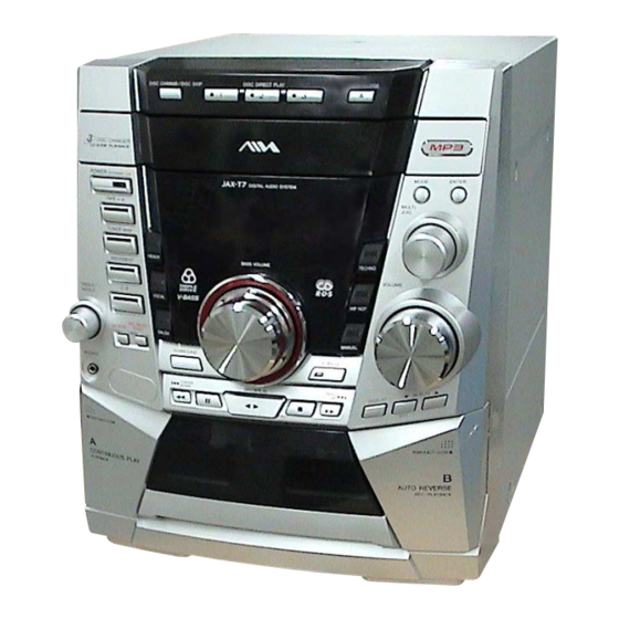
Aiwa CX-JT7 Service Manual (92 pages)
COMPACT DISC DECK RECEIVER
Brand:
Aiwa
| Category:
Stereo System
| Size: 10.11 MB
Table of Contents
Table of Contents
3
1 Servicing Notes
4
2 General
7
Location of Controls
7
3 Disassembly
9
Disassembly Flow
9
Case (SIDE-L/R)
10
Case (Top)
10
Tray Panel
11
CD Mechanism Deck (CDM74F-K6BD71A)
11
Front Panel Section
12
Mechanical Deck
12
Rear Cabinet Section
13
MAIN Board
13
POWER Board
14
TRANSFORMER Board
14
Motor (TB) Board
15
Motor (LD) Board
16
Base Unit (BU-K6BD71A)
16
Motor Gear Assy (Sled) (M701), BD Board
17
Optical Pick-Up (KSS-213D)
17
4 Test Mode
18
5 Electrical Adjustments
21
CD Section
21
6 Diagrams
22
Block Diagram - CD Section
22
Block Diagram - TUNER/TAPE/PANEL Section
23
Block Diagram - AMP/POWER SUPPLY Section
24
Note for Printed Wiring Boards and Schematic Diagrams
25
Printed Wiring Board - BD Board
26
Schematic Diagram - BD Board
27
Printed Wiring Boards - CHANGER Section
28
Schematic Diagram - CHANGER Section
29
Schematic Diagram - MAIN Board (1/4) (Suffix-11)
30
Schematic Diagram - MAIN Board (2/4) (Suffix-11)
31
Schematic Diagram - MAIN Board (3/4) (Suffix-11)
32
Schematic Diagram - MAIN Board (4/4) (Suffix-11)
33
Printed Wiring Board - MAIN Board (Suffix-11)
34
Printed Wiring Board - MAIN Board (Suffix-13)
35
MAIN Board (1/4) (Suffix-13)
36
Schematic Diagram - MAIN Board (2/4) (Suffix-13)
37
Schematic Diagram - MAIN Board (3/4) (Suffix-13)
38
Schematic Diagram - MAIN Board (4/4) (Suffix-13)
39
PRINTED WIRING BOARDS - CD BUTTON/HEADPHONE/MICROPHONE Boards
40
MICROPHONE Boards
41
Printed Wiring Board - PANEL Board
42
Schematic Diagram - PANEL Board
43
Schematic Diagram - POWER Board (1/2)
44
Schematic Diagram - POWER Board (2/2)
45
Printed Wiring Board - POWER Board - (AEP, UK, CIS Models)
46
Printed Wiring Board - POWER Board - (MX Model)
47
Printed Wiring Board - POWER Board - (E51 Model)
48
Printed Wiring Board - TRANSFORMER Board - (AEP, UK, CIS Models)
49
Printed Wiring Board - TRANSFORMER Board
50
(MX Model)
50
Printed Wiring Board - TRANSFORMER Board
51
(E51 Model)
51
Schematic Diagram - TRANSFORMER Board - (AEP, UK, CIS, E51 Models)
52
Schematic Diagram - TRANSFORMER Board - (MX Model)
53
IC Pin Function Description
57
7 Exploded Views
63
Case Section
63
Front Panel Section-1
64
Front Panel Section-2
65
Front Panel Section-3
66
Front Panel Section-4
67
Chassis Section-1
68
Chassis Section-2
69
CD Mechanism Deck Section-1 (CDM74F-K6BD71A)
70
CD Mechanism Deck Section-2 (CDM74F-K6BD71A)
71
CD Mechanism Deck Section-3 (CDM74F-K6BD71A)
72
Base Unit Section (BU-K6BD71A)
73
8 Electrical Parts List
74
Abbreviation
74
E51 : Chilean and Peruvian Models
74
MX : Mexican Model
74
Advertisement
Advertisement
Related Products
Aiwa CX-JT9
Aiwa CX-JT8
Aiwa CX-JV4
Aiwa CX-JDS33
Aiwa CX-JN55
Aiwa CX-JPK33
Aiwa CX-JV77
Aiwa CX-JE3
Aiwa CX-JDS55
Aiwa CX-J3000M
Aiwa Categories
Stereo System
Cassette Player
CD Player
Car Receiver
Stereo Receiver
More Aiwa Manuals
Login
Sign In
OR
Sign in with Facebook
Sign in with Google
Upload manual
Upload from disk
Upload from URL