Sign In
Upload
Manuals
Brands
Airbus Manuals
Car Receiver
TMR880i
User Manuals: Airbus TMR880i Mobile TETRA Radio
Manuals and User Guides for Airbus TMR880i Mobile TETRA Radio. We have
2
Airbus TMR880i Mobile TETRA Radio manuals available for free PDF download: Installation Instructions Manual
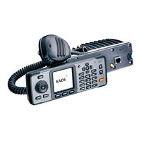
Airbus TMR880i Installation Instructions Manual (60 pages)
TETRA Mobile Radio
Brand:
Airbus
| Category:
Car Receiver
| Size: 2 MB
Table of Contents
Table of Contents
3
1 General Information
8
Contact
8
Figure 1. Tmr880I TETRA Mobile Radio
8
2 Technical Specifications
9
Table 1. Technical Specifications
9
3 Sales Packages for Tmr880I
10
Radio Sales Package
10
Control Unit Cur-3 Sales Package
10
Two Configurations with System Cables
10
Enhanced Configuration with CA-105 Cable
11
Figure 2. Enhanced Configuration with CA-105 Cable
11
Basic Configuration with CA-156 Cable
12
Figure 3. Basic Configuration with CA-156 Cable
12
Use Without Cur-3
13
Figure 4. Use with CUR-3
13
4 Accessories for Vehicle Installation
14
Handset (Hsu-6)
15
Handsfree Microphone (Hfr-1)
15
Figure 5. Handset HSU-6 (Left) and Phased-Out Model HSU-1T (Right)
15
Figure 6. Connected Handset HSU-6
15
Handsfree Push-To-Talk Button (PTT-1)
16
Data Cable (Dlr-3T)
16
Figure 7. Handsfree Microphone HFR-1
16
Figure 8. Handsfree Push to Talk Button PTT-1
16
Figure 9. Data Cable DLR-3T
16
Antennas (An-58, An-59 and An-60)
17
Installation Cables
17
Power Supply (Acr-7E, Acr-7U, Acr-7X) for Office Use
17
Table 2. CUR-3 Installation Cables
17
Figure 10. CUR-3 Installation Cables
17
Figure 11. Power Supply for Office Use ACR-7 (Left) and ACR-1 (Right)
17
Speaker Microphone (Mpr-4)
18
Loudspeaker (Hfs-10)
18
Loudspeaker 15W (Hfs-11)
18
Figure 12. Speaker Microphone MPR-4 (Left) and Phased-Out MPR-1 (Right)
18
Figure 13. Loudspeaker HFS-10
18
Swivel Mount (Hhr-1) for Control Unit Cur-3
19
Other Parts
19
Installation Plate
19
Figure 14. Loudspeaker HFS-11
19
Figure 15. Swivel Mount for CUR-3
19
Figure 16. Installation Plate
19
Fuse 5A 125°C Rated
20
Start-Stop Plug (SS-4)
20
Figure 17. Fuse
20
Figure 18. Start-Stop Plug for Tmr880I
20
5 Connectors and Pin Layouts
21
Connectors in the Back-Front
21
Figure 19. Back-Front Connectors
21
Connectors in the Front Panel
22
Connectors in Cur-3
22
Figure 20. Front Panel Connectors
22
Audio Accessory Use
23
Speaker Microphone Cable and Connector Options
23
Speaker Microphone (MPR-4)
23
Figure 21. MPR-4 Connector
23
Old Model Speaker Microphone (MPR-1)
24
Table 3. Technical Data of the MPR-4 Connector
24
Figure 22. Speakermic MPR-4 Connector
24
System Cable Connector
25
Figure 23. Face View of 12-Pin Hirose Connector
25
Table 4. System Cable Connector
26
Figure 24. Face View of 26-Pin High Density D Connector (Radio Part) X1
26
Table 5. CA-105 Power Cable Interface
28
Figure 25. CA-105/156 System Connector Interface
28
Table 6. Connections in X100 (Handset Connector in X2)
31
Figure 26. Face-View of Integrated DTC-1 (X2)
31
Table 7. Connections in X200 (Data Cable Connection in X2)
32
Control Unit Interface Connector
33
Table 8. Control Unit Interface Connector
33
Figure 27. Face View of 26-Pin High Density D Connector (Radio Part)
33
I/O Auxiliary Accessory Connector
34
Figure 28. Face View of 26-Pin High Density D Connector (Radio Part)
34
Table 9. I/O Auxiliary Accessory Connector
35
Figure 29. Face View of 26-Pin High Density D Connector (Radio Part)
35
External Smart Card Connector
36
Active Gps Antenna Connector
36
Tetra Antenna Connector
36
Figure 30. Face View of RJ45 Smart Card Reader (Radio Part)
36
Figure 31. Face View of SMA GPS Antenna (Radio Part)
36
Figure 32. Face View of TNC TETRA Antenna (Radio Part)
36
Smart Card Connector
37
Figure 33. Face View of Smart Card Connector (Radio Part)
37
6 Installing Tmr880I
38
Installing the Antenna
38
Selecting the Antenna Site
38
Installing the Antenna
39
Assembling Cur-3
39
Assembling the Installation Cable
39
Connecting the Speaker Microphone Cable (Used with MPR-4)
40
Figure 34. CUR-3 Installation Cable
40
Figure 35. Connecting the CUR-3 Installation Cable
40
Attaching the CUR-3 Assembly Swivel (HHR-1)
41
Figure 36. Fastened Cable Cover, with System Cable and CA-157 Speaker Microphone Cable
41
Figure 37. CA-157 Adapter Cable with RJ-45 Connector
41
Figure 38. Complete Swivel (HHR-1)
41
Figure 39. Swivel Fastening (Fixed Mounting Kit, MKE-1BK)
42
Figure 40. Fastening the Swivel
42
Figure 41. Fastened Swivel
42
Installing Cur-3 into Din Slot by Using the Din Slot Installation Set
43
Preparing the DIN Slot Installation Bracket
43
Figure 42. DIN Slot Installation Bracket
43
Figure 43. Electrical Unlocking
43
Preparing the DIN Slot Installation Adapter
44
Figure 44. Manual Unlocking
44
Figure 45. Bent Fixing Tabs
44
Attaching CUR-3 into the DIN Slot Installation Set
45
Figure 46. Fastening the Swivel
45
Figure 47. Mounting and Locking the DIN Slot Installation
45
Figure 48.Attaching the Swivel into the CUR-3
45
Installing Tmr880I by Using an Installation Plate
46
Figure 49. Attaching CUR-3 into the DIN Slot Installation Set
46
Figure 50. Installation Kit
46
Figure 51. Installation Plate
46
Power Distribution
47
Figure 52. Maximum Inclination
47
Grounding
48
IGN Power On/Off Control
48
Figure 53. System Cable CA-105 Interfaces
49
System Cable CA-105 Interfaces
49
Table 10. System Cable CA-105 Connectors
49
Shortening the Installation Cable (Ca-103, Ca-104, Ca-108)
50
Table 11. System Cable CA-105'S Length
50
Table 12. System Cable CA-105'S Diameter
50
Figure 54. Appearance of the Installation Cable
51
Figure 55. Appearance of Installation Cable X1
51
Table 13. X1 Connector's Pins and Connections
52
Figure 56. X1 Connector's Circuit Diagram
52
7 Programming in the Taqto Tool
54
Figure 57. Connecting the Programming Cable
54
8 Installing the Helmet Cable
56
Circuit Diagram
56
Figure 58. CA-103/CA-104/CA-108/CA-116 Installation Cable and CA-106 Helmet Cable Assembly
56
Detailed Description of the Helmet Interface
57
Microphone Input Interface
57
Figure 59. Circuit Diagram of Helmet Cable
57
Figure 60. Helmet Cable Microphone's Input Flowchart
57
Electrical Specifications
58
Modifications for a Dynamic Microphone
58
Selecting the Electret Microphone Capsule
58
Speaker Output Interface
58
Table 14. Microphone Input Electrical Specifications
58
Figure 61. Speaker Output Flowchart
58
Electrical Specifications
59
Control Signals
59
Table 15. Speaker Output Electrical Specifications
59
Table 16. Control Signals
59
Technical Specification
60
Table 17. Connections in X1 (Helmet Cable Connector)
60
Advertisement
Airbus TMR880i Installation Instructions Manual (59 pages)
TETRA Mobile Radio
Brand:
Airbus
| Category:
Radio
| Size: 4 MB
Table of Contents
Table of Contents
3
1 General Information
8
Contact
8
Figure 1. Tmr880I TETRA Mobile Radio
8
2 Technical Specifications
9
Table 1. Technical Specifications
9
3 Sales Packages for Tmr880I
10
Sales Package Option 1
10
Sales Package Option 2
11
Radio Sales Package
11
Operation Without Cur-3 from a Tablet or Pc
11
4 Optional External Audio Accessories
12
Optional Data Accessories
12
5 Accessories for Office Installation
13
Table 2. Accessory Reference List
13
Handset (Hsu-6)
14
Handsfree Microphone (Hfr-1)
14
Figure 2. Handset HSU-6 (Left) and Phased-Out Model HSU-1T (Right)
14
Figure 3. Connected Handset HSU-6
14
Handsfree Push-To-Talk Button (PTT-1)
15
Data Cable (Dlr-3T)
15
Figure 4. Handsfree Microphone HFR-1
15
Figure 5. Handsfree Push to Talk Button PTT-1
15
Figure 6. Data Cable DLR-3T
15
Antenna (An-60)
16
Installation Cables
16
Power Supply (Acr-7E, Acr-7U, Acr-7X) for Office Use
16
Table 3. CUR-3 Installation Cables
16
Figure 7. CUR-3 Installation Cables
16
Figure 8. Power Supply for Office Use ACR-7 (Left) and ACR-1 (Right)
16
Speaker Microphone (Mpr-4)
17
Loudspeaker (Hfs-10)
17
Loudspeaker 15W (Hfs-11)
17
Figure 9. Speaker Microphone MPR-4 (Left) and Phased-Out MPR-1 (Right)
17
Figure 10. Loudspeaker HFS-10
17
Desktop Gooseneck Microphone Dgm-1
18
Figure 11. Loudspeaker HFS-11
18
Figure 12. Gooseneck Microphone DGM-1
18
Swivel Mount (Hhr-1) for Control Unit Cur-3
19
Other Parts
19
Installation Plate
19
Figure 13. Swivel Mount for CUR-3
19
Figure 14. Installation Plate
19
Fuse 5A 125°C Rated
20
Figure 15. Fuse
20
6 Connectors and Pin Layouts
21
Connectors in the Back-Front
21
Figure 16. Back-Front Connectors
21
Connectors in the Front Panel
22
Connectors in Cur-3
22
Figure 17. Front Panel Connectors
22
Audio Accessory Use
23
Speaker Microphone Cable and Connector Options
23
Speaker Microphone (MPR-4)
23
Figure 18. MPR-4 Connector
23
Table 4. Technical Data of the MPR-4 Connector
24
Figure 19. Speakermic MPR-4 Connector
24
System Cable Connector
25
Table 5. System Cable Connector
25
Figure 20. Face View of 26-Pin High Density D Connector (Radio Part) X1
25
Table 6. CA-105 Power Cable Interface
27
Figure 21. CA-105/156 System Connector Interface
27
Table 7. Connections in X100 (Handset Connector in X2)
30
Figure 22. Face-View of Integrated DTC-1 (X2)
30
Table 8. Connections in X200 (Data Cable Connection in X2)
31
Control Unit Interface Connector
32
Table 9. Control Unit Interface Connector
32
Figure 23. Face View of 26-Pin High Density D Connector (Radio Part)
32
I/O Auxiliary Accessory Connector
33
Figure 24. Face View of 26-Pin High Density D Connector (Radio Part)
33
Table 10. I/O Auxiliary Accessory Connector
34
Figure 25. Face View of 26-Pin High Density D Connector (Radio Part)
34
External Smart Card Connector
35
Active Gps Antenna Connector
35
Tetra Antenna Connector
35
Figure 26. Face View of RJ45 Smart Card Reader (Radio Part)
35
Figure 27. Face View of SMA GPS Antenna (Radio Part)
35
Figure 28. Face View of TNC TETRA Antenna (Radio Part)
35
Smart Card Connector
36
Figure 29. Face View of Smart Card Connector (Radio Part)
36
7 Installing Tmr880I
37
Overview
37
Installing the Antenna
37
Selecting the Antenna Site
37
Installing the Antenna
38
Assembling Cur-3
39
Assembling the Installation Cable
39
Figure 30. CUR-3Installation Cable
39
Connecting the Speaker Microphone Cable (Used with MPR-4)
40
Figure 31. Connecting the CUR-3 Installation Cable
40
Figure 32. Fastened Cable Cover, with System Cable and CA-157 Speaker Microphone Cable
40
Tools Needed for Disassembling and Assembling
41
Figure 33. CA-157 Adapter Cable with RJ-45 Connector
41
Figure 34. Main Assembly of Desktop
42
8 Assembling the Dk Kit
43
Assembling the A-Cover
43
Figure 35. A-Cover
43
Figure 36. Fixing Plate
43
Figure 37. Mounting the Fixing Plate
44
Figure 38. Radio Part
44
Figure 39. Mounting the Radio
44
Figure 40. CUR-3 Control Unit
45
Figure 41. Swivel Mount
45
Figure 42. Attaching the Swivel Mount to CUR-3
45
Figure 43. Attaching the Swivel Body
46
Figure 44. Swivel Mount and CUR-3 Cable
46
Figure 45. CUR-3 and HFS-10 to A-Cover
46
Figure 46. HFS11 Mount (OPTION) to A-Cover
47
Figure 47. HFS-10 to A-Cover
47
Figure 48. HFS-11 (OPTION) to A-Cover
47
Assembling the B-Cover
48
Overview
48
Figure 49. MPR-4 Holder to A-Cover
48
Figure 50. MPR-4 Cable Clamp
48
Figure 50. B-Cover
48
Installing the Power Supply Unit
49
Figure 51. Fixing the Power Supply Unit
49
Figure 52. System Cable
49
IGN Power On/Off Control
50
Figure 53. Preparing the System Cable
50
Figure 54. Fuses to the System Cable
50
Final Assembly Instructions
51
Figure 55. Connecting the Supply Wires
51
Figure 56. Protecting the Supply Wires
51
Figure 57. Connecting Loudspeaker and Handset
51
Figure 58. Cables to B-Cover
52
Figure 59. Assembling the A- and B-Covers
52
Figure 60. Connecting Tmr880I Backplane Connectors
53
Figure 61. Mounting the A- and B-Covers
53
Figure 62. Connecting the Speaker Microphone
53
Installing HSU-6 (Optional Item)
54
Figure 63. Handset
54
Figure 64. Handset Fixing Plate to A-Cover
54
Figure 65. Handset to A-Cover
54
9 Functional Testing
55
Figure 66. Checking the Power Supply and Supply Connection
55
Figure 67. Handset Functionality Check
55
Figure 68. Speaker Microphone Functionality Check
56
10 Configuring Optional Connections
57
11 Programming in the Taqto Tool
58
Figure 69. Connecting the Programming Cable CA-122
58
Advertisement
Related Products
Airbus Tactilon Dabat
Airbus THR9 Ex
Airbus TW1m
Airbus TPH900 Series
Airbus TDM880i
Airbus Categories
Aircrafts
Automobile Accessories
Radio
Modem
Switch
More Airbus Manuals
Login
Sign In
OR
Sign in with Facebook
Sign in with Google
Upload manual
Upload from disk
Upload from URL