Sign In
Upload
Manuals
Brands
Aim Manuals
Network Hardware
ANET1553 Series
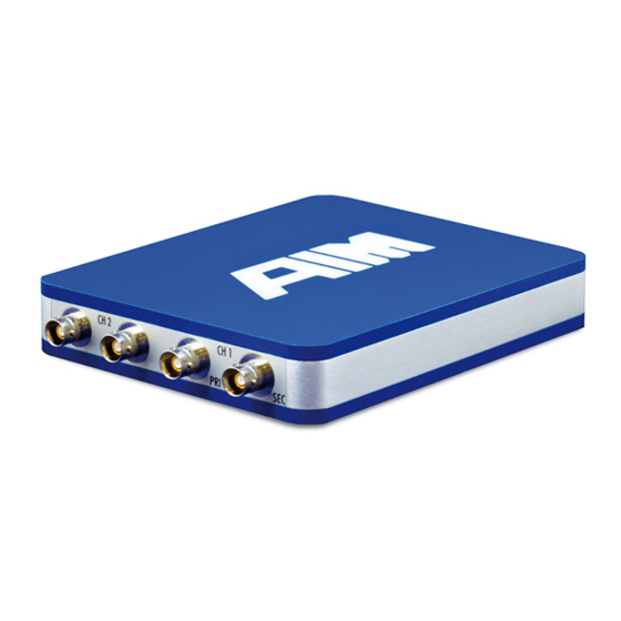
User Manuals: Aim ANET1553 Series Ethernet Module
Manuals and User Guides for Aim ANET1553 Series Ethernet Module. We have
1
Aim ANET1553 Series Ethernet Module manual available for free PDF download: User Manual
Aim ANET1553 Series User Manual (72 pages)
Single or Dual Stream MIL-STD-1553A/B Test & Simulation Module for Standard Ethernet
Brand:
Aim
| Category:
Network Hardware
| Size: 2 MB
Table of Contents
Table of Contents
7
1 Introduction
11
General
11
Applicable Documents
12
Industry Documents
12
Product Specific Documents
12
2 Installation
13
BSP Installation
13
Figure 2.1-1 BSP Setup
14
Hardware Installation
16
Connectors
16
Figure 2.2-1 Front Panel
16
Figure 2.2-2 Back Panel
17
Figure 2.2-3 TWINAX Connector
17
MIL-STD-1553 Interface Connectors
17
Auxiliary Connector HD DSUB15
18
DC Power in Connector
18
Figure 2.2-4: Auxiliary Connector
18
Figure 2.2-5: DC Panel Socket
18
RJ45 Ethernet Connector
18
Table 2.2.1-1 Pinout Auxiliary Connector
18
USB TYP-A Host Connector
18
Module-Powering and Status Indication (Led's)
19
Ethernet RJ45 Status Indicator
19
Module Status Indicator
19
Powering the Module
20
3 Getting Started
21
Requirements
21
Integration in a Network
21
The Network Provides a DHCP Sever
21
The Network Doesn't Provide a DHCP Sever
21
The AIM Network Detection Tool
22
Installing Apple Bonjour
22
Figure 2.2-1 Apple Bonjour
22
Figure 2.2-2 Apple Bonjour Support
22
Using the AIM Network Detection Tool
23
Figure 2.2-3 AIM Network Detection Tool
23
Configuring the ANET1553
24
Figure 2.2-4 ANET Web Configuration Tool "System Overview
24
Configuring Basic Properties
25
Setting the IP-Address
25
Figure 2.2-5 ANET Web Configuration Tool "General Settings
25
Figure 2.2-6 ANET Web Configuration Tool "Network Settings
25
Configuring Wireless Network Interfaces
26
Figure 2.2-7 ANET Wireless Network Device Configuration
27
Configure System Services
29
Discrete I/O State
29
Figure 2.2-8 ANET Web Configuration Tool "Services
29
Figure 2.2-9 ANET Web Configuration Tool "Discrete I/O
29
Check System Log-File
30
Re-Boot or Shutdown over Ethernet
30
Reset Settings to Factory Default
30
Updating the ANET1553 Module
31
Figure 2.2-10 ANET Web Configuration Tool "Maintenance
31
Figure 2.2-11 ANET Web Configuration Tool "Update Tab
31
Figure 2.2-12 ANET Web Configuration Tool "Update Is Running
32
Figure 2.2-13 ANET Web Configuration Tool "Update Finished
33
Figure 2.2-14 ANET Web Configuration Tool "Update Log-File
33
Booting the Device into Emergency Mode
34
How to Connect Applications to the ANET1553
34
Connect to a ANET1553 with Pba.pro
34
Figure 2.2-15 Emergency Boot Button
34
Figure 2.2-16 Connect to ANET1553 with Pba.pro
35
Figure 2.2-17 Connect to ANET1553 with Pba.pro
35
Connect to a ANET1553 Using the AIM API-Library
36
Connecting the ANET1553 to the MIL-STD-1553 Bus
36
Direct Coupling
37
Figure 2.2-18 Pigtail Connector
37
Figure 2.2-19 Direct Coupling
37
Transformer Coupling
38
Figure 2.2-20 Stub Coupler
38
Figure 2.2-21 Transformer Coupling
38
Figure 2.2-22 Transformer Coupling
38
Network Emulation Coupling
39
Isolated Coupling
39
Figure 2.2-23 Network Emulation Coupling
39
4 Structure of the ANET1553
41
Figure 2.2-1 Block Diagram ANET1553-2
41
System FPGA
42
Global RAM
42
BIU Section
42
MIL-STD-1553 Encoder
42
MIL-STD-1553 Decoder
42
External Trigger Inputs and Outputs
43
Physical MIL-STD-1553B I/O Interface, Milbus Coupling Modes
43
Figure 4.4-1 Coupling Modes
43
ASP Section
44
Discrete I/Os
44
Figure 4.4-2 Diagram Milbus Output Amplitude Versus Amplitude Settings
44
Figure 4.6-1 Discrete I/O Circuitry
45
Figure 4.6-2 Discrete I/O-Pin off Board User Series Resistor
46
IRIG- and Time Code Section
47
Timecode Encoder/Decoder
47
Table 4.7.1-1 Time Tag Format
47
Time Tag Methods
48
5 Compiling and Running a Sample Project
49
Figure 4.7-1 File Structure Sample Project
50
Figure 4.7-2 Sample Project Search Paths
50
Figure 4.7-3 Sample Project Preprocessor Definitions
51
Figure 4.7-4 Sample Project Library Path
52
6 Single or Simulator Only Functions
53
Simulator Only Versions
53
Single Function Version
53
7 Frequently Asked Questions
55
8 Technical Data
57
9 Notes
61
Acronyms
61
10 Apendix
63
ANET Table Adapter Panel (for ANET '-D' Variants)
63
How to Connect the ANET Table Adapter
63
Figure 10.1-1 ANET Table Adapter Pinout
63
Figure 10.2-1 ANET Docking Connector
63
Figure 10.2-2 ANET Table Adapter
63
ANET Rugged Housing Variant
66
Hardware Installation
66
Connectors
66
DC Power IN-, Reset- and Power up Control- Connector
67
Table 10.3.3-1 Pinout Power Connector
67
MIL-STD-1553 Interface Connector
68
Figure 10.3-1 MIL-STD-1553 Connector (Front View)
68
Table 10.3.4-1 Pinout MIL-STD-1553 Interface Connector
68
Module Status Indicator and Powering
69
Module Status Indicator
69
Powering the Module
70
Power Debug Cable
70
Technical Data for the Rugged Variant
71
Certificate of Volatility
72
Advertisement
Advertisement
Related Products
Aim ANET1553-2
Aim ANET1553-1
Aim ANET42
Aim AXC-FDX-2
Aim AVC429
Aim ACP-1
Aim AMCX-FDX-2
Aim ACPe-1
Aim AVC-2
Aim AVC-2-CC
Aim Categories
Data Loggers
Automobile Accessories
Control Unit
Computer Hardware
Motorcycle Accessories
More Aim Manuals
Login
Sign In
OR
Sign in with Facebook
Sign in with Google
Upload manual
Upload from disk
Upload from URL