Sign In
Upload
Manuals
Brands
Agilent Technologies Manuals
Measuring Instruments
N5230C
Agilent Technologies N5230C Manuals
Manuals and User Guides for Agilent Technologies N5230C. We have
1
Agilent Technologies N5230C manual available for free PDF download: Service Manual
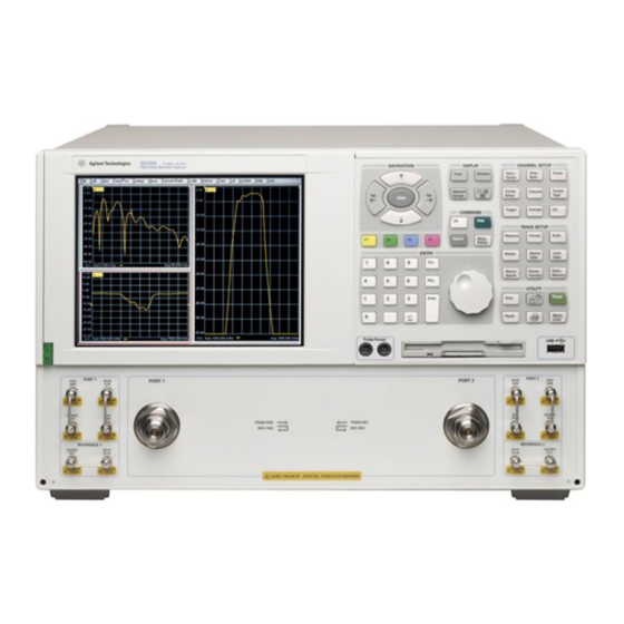
Agilent Technologies N5230C Service Manual (282 pages)
2-Port PNA-L Microwave Network Analyzer (10 MHz–20/40/50 GHz)
Brand:
Agilent Technologies
| Category:
Measuring Instruments
| Size: 8.7 MB
Table of Contents
Service Guide N5230-90024
3
Table of Contents
5
1 Safety and Regulatory Information
11
Information in this Chapter
12
Chapter One At-A-Glance
12
Safety Symbols
13
General Safety Considerations
13
Safety Earth Ground
13
Before Applying Power
13
Servicing
14
Electrostatic Discharge Protection
16
Regulatory Information
17
Instrument Markings
18
Lithium Battery Disposal
19
2 General Product Information
21
Information in this Chapter
22
Chapter Two At-A-Glance
22
Maintenance
23
Physical Maintenance
23
Electrical Maintenance
23
Analyzer Options Available
23
Options as Upgrades
23
Understanding Your Analyzer's Option Numbers
23
Option 010, Time Domain
24
Option 014, Configurable Test Set
24
Option 080, Frequency Offset Mode
24
Option 1CM, Rack Mount Flange Kit for Instruments Without Handles
24
Option 1CP, Rack Mount Flange Kit for Instruments with Handles
24
Option 1E1, Source Attenuators (Extended Power Range)
25
Option 897, Built-In Tests for Commercial Calibration
25
Option 898 Built-In Tests for Standards Compliant Calibration
25
Option F20, 20 Ghz Frequency Range
25
Option F40, 40 Ghz Frequency Range
25
Option F50, 50 Ghz Frequency Range
25
Analyzer Accessories and Upgrades Available
26
Pulse I/O Adapter-N1966A
26
Required Service Test Equipment
27
Agilent Support, Services, and Assistance
30
Service and Support Options
30
Contacting Agilent
30
Shipping Your Analyzer to Agilent for Service or Repair
31
3 Tests and Adjustments
33
Information in this Chapter
34
Chapter Three At-A-Glance
34
Before You Begin
36
Verify the Operating Environment
36
Protect against Electrostatic Discharge (ESD)
36
Allow the Analyzer to Warm up
36
Review the Principles of Connector Care
37
About System Verification and Performance Tests
38
System Specifications
38
Instrument Specifications
38
System Verification Procedure
38
Performance Tests
39
Certificate of Calibration
39
ANSI/NCSL Z540-1-1994 Verification
40
Non-ANSI/NCSL Z540-1-1994 Verification
41
Preliminary Checks
42
The Operator's Check
42
The Test Port Cable Checks
44
System Verification
51
What the System Verification Verifies
51
Measurement Uncertainty
52
Measurement Traceability
53
Performing System Verification
54
Performance Tests (Agilent N7840A Software Package)
60
Source Power Accuracy Test
60
Source Maximum Power Output Test
61
Source Power Linearity Test
61
Frequency Accuracy Test
62
Trace Noise Test
62
Receiver Compression Test
63
Noise Floor Test
63
Calibration Coefficients Test
65
Dynamic Accuracy Test
66
Adjustments
67
10 Mhz Frequency Reference Adjustment
67
EE Default Adjustment
68
LO Power Adjustment
68
Source Calibration Adjustment
70
Receiver Calibration Adjustment
71
4 Troubleshooting
75
Information in this Chapter
76
Chapter Four At-A-Glance
76
Protect against Electrostatic Discharge (ESD)
77
Assembly Replacement Sequence
77
Getting Started with Troubleshooting
78
Check the Basics
78
Troubleshooting Organization
79
Power up Troubleshooting
80
Power Supply Check
81
Front Panel Troubleshooting
86
Front Panel Keypad and RPG Test
87
A2 Display Test
89
Checking the USB Board
90
A3 Front Panel Interface Board
90
Rear Panel Troubleshooting
91
Checking the USB Ports
91
Checking the SERIAL (RS-232), PARALLEL (1284-C), or VGA Port
92
Checking the GPIB Port
92
LAN Troubleshooting
93
Measurement System Troubleshooting
97
Before You Begin-Consider: Where Do You See a Problem
97
Verifying the A, B, R1, and R2 Traces (Standard S-Parameter Mode)
100
Where to Begin Troubleshooting
101
Checking the Source Group
103
Checking the Signal Separation Group
110
Checking the Receiver Group
114
Instrument Block Diagrams Sheet 1
117
Instrument Block Diagrams Sheet 2
117
5 Theory of Operation
119
Information in this Chapter
120
Chapter Five At-A-Glance
120
Network Analyzer System Operation
121
Functional Groups of the Network Analyzer
121
Synthesized Source Group Operation
124
Basic Operation
124
Frequency Offset Operation (Option 080)
127
A7 and A9 Fractional-N Synthesizer Boards
127
A6 and A8 Multiplier Boards
127
A17 Multiplier/Amplifier/Switch/Splitter 26.5 (MASS 26.5)
127
A18 Multiplier/Amplifier 26.5 (MA 26.5)
127
A19 Multiplier/Amplifier/Switch/Splitter 50 (MASS 50)
128
A10 Frequency Reference Board
128
A16 Test Set Motherboard
129
Signal Separation Group Operation
133
A17 Multiplier/Amplifier/Switch/Splitter 26.5 (MASS 26.5)
134
A19 Multiplier/Amplifier/Switch/Splitter 50 (MASS 50)
134
A21 and A22 Test Port Couplers
134
A25 and A26 60-Db Source Step Attenuators (Option 1E1)
134
Configurable Test Set (Option 014)
134
Receiver Group Operation
137
A20 Mixer Brick
137
A5 SPAM Board (Analog Description)
137
Digital Processing and Digital Control Group Operation
139
Front Panel Subgroup
141
Data Acquisition and Processing Subgroup
142
Power Supply Group Operation
144
6 Replaceable Parts
145
Information in this Chapter
146
Chapter Six At-A-Glance
146
Ordering Information
147
Assembly Replacement Sequence
148
Rebuilt-Exchange Assemblies
149
Replaceable Parts Listings
150
Front Panel Assembly, Front Side, All Options
152
Front Panel Assembly, Back Side, All Options
154
Top Assemblies, All Options
156
Top Cables, All Options
158
Bottom Assemblies, Option 220
160
Bottom Cables, Option 220
162
Bottom Assemblies, Option 225
164
Bottom Cables, Option 225
166
Bottom Assemblies, Options 420 and 520
168
Bottom Cables, Options 420 and 520
170
Bottom Assemblies, Options 425 and 525
172
Bottom Cables, Options 425 and 525
174
Top Hardware and Miscellaneous Parts, All Options
176
Bottom Hardware and Miscellaneous Parts, All Options
178
Internal Hardware and Miscellaneous Parts, All Options
180
External Hardware and Miscellaneous Parts, All Options
182
Rear Panel Assembly, All Options
184
Hard Disk Drive Assembly, All Options
186
Miscellaneous Part Numbers
190
7 Repair and Replacement Procedures
193
Information in this Chapter
194
Chapter Seven At-A-Glance
194
Personal Safety Warnings
195
Electrostatic Discharge (ESD) Protection
195
Assembly Replacement Sequence
196
Removal and Replacement Procedures
197
Removing the Covers
198
Removing and Replacing the Front Panel Assembly
200
Removing and Replacing Front Panel Subassemblies
202
Removing and Replacing the A4 Power Supply Assembly
206
Removing and Replacing the A5 through A10 Boards and the Plenum Bracket
208
Removing and Replacing the A14 System Motherboard
210
Removing and Replacing the A15 CPU Board
212
Removing and Replacing the A16 Test Set Motherboard and the USB Hub
216
Removing and Replacing the A17 MASS 26.5
218
Removing and Replacing the A18 MA 26.5
220
Removing and Replacing the A19 MASS 50
222
Removing and Replacing the A20 Mixer Brick
224
Removing and Replacing the A21 and A22 Test Port Couplers
226
Removing and Replacing the A21 and A22 Test Port Couplers
228
Removing and Replacing the A25 and A26 60-Db Source Step Attenuators (Option 1E1)
230
Removing and Replacing the A41 Hard Disk Drive (HDD)
232
Removing and Replacing the Midweb and the B1 Fan(S)
240
Removing and Replacing the Lithium Battery
244
Post-Repair Procedures
246
8 General Purpose Maintenance Procedures
249
Information in this Chapter
250
Chapter Eight At-A-Glance
250
Error Terms
251
Using Error Terms as a Diagnostic Tool
251
Performing Measurement Calibration
251
Using Flowgraphs to Identify Error Terms
252
Accessing Error Terms
256
Error Term Data
258
Option Enable Utility
262
Accessing the Option Enable Utility
262
Enabling or Removing Options
263
Repairing and Recovering Option Data
264
Installing or Changing a Serial Number
265
Firmware Upgrades
266
How to Check the Current Firmware Version
266
Downloading from the Internet
266
Operating System Recovery
267
Recovering from Hard Disk Drive Problems
267
Correction Constants
268
Storing Correction Constants
268
Advertisement
Advertisement
Related Products
Agilent Technologies N5230A
Agilent Technologies N5242A
Agilent Technologies N5241A
Agilent Technologies N5225-60114
Agilent Technologies N5531S
Agilent Technologies N5502A
Agilent Technologies N9010A
Agilent Technologies FieldFox N9937A
Agilent Technologies N2600A
Agilent Technologies N7744A
Agilent Technologies Categories
Measuring Instruments
Laboratory Equipment
Test Equipment
Water Pump
Power Supply
More Agilent Technologies Manuals
Login
Sign In
OR
Sign in with Facebook
Sign in with Google
Upload manual
Upload from disk
Upload from URL