Sign In
Upload
Manuals
Brands
Agilent Technologies Manuals
Test Equipment
E4406-90178
Agilent Technologies E4406-90178 Manuals
Manuals and User Guides for Agilent Technologies E4406-90178. We have
1
Agilent Technologies E4406-90178 manual available for free PDF download: Service Manual
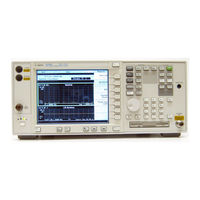
Agilent Technologies E4406-90178 Service Manual (266 pages)
Transmitter Tester
Brand:
Agilent Technologies
| Category:
Test Equipment
| Size: 8.19 MB
Table of Contents
Table of Contents
5
Introduction
12
Before You Start
13
Replacement Assemblies
14
After an Instrument Repair
14
ESD Information
15
Service Equipment You will Need
18
Check the Basics
23
Problems at Instrument Power-Up
25
Troubleshooting an Inoperative Instrument
26
Check the Instrument Setup
26
Initial Checks
26
If the Fans Are Not Operating
27
Troubleshooting LCD Display Problems
28
Verifying the A3A1 and A3A2 Inverter Boards
28
Verifying HSYNC, VSYNC, and LCD Clock
30
Check for Basic Functionality
31
Auto-Align Tests
32
Power Supply Check
34
Measure the Individual Voltage Supplies
35
Isolating an RF, Analog IF, Digital IF, Reference, Synthesizer, or CPU Problem
39
Verifying the A17 RF Assembly
39
Verifying the A12 Analog if Assembly
43
Verifying the A10 Digital if Assembly
47
Verifying the A18 Reference Assembly
50
Verifying the A19 Synthesizer Assembly
52
Verifying the A22 CPU Assembly
54
Troubleshooting Performance Test Failures
58
Contacting Agilent Technologies
60
Software Technical Support
60
Calling Agilent Technologies Sales and Service Offices
60
Updating Firmware
63
How to Return Your Instrument for Service
64
Service Tag
64
Original Packaging
64
Other Packaging
65
2 Block Diagrams
67
Introduction
68
A6 Power Supply Assembly
69
A17 RF Assembly
70
Input Attenuator
70
RF Input Switch
70
321.4 Mhz Amplifiers
71
50 Mhz Calibrator
71
Calibrator Switch
71
First Mixer
71
Image Filter
71
Second Mixer
71
21.4 Mhz Output Buffer Amplifiers and Filter
72
Pre-Level Drive
72
Interconnections to Other Assemblies
72
A12 Analog if Assembly
73
Pre-Filters
73
Variable Gain Amplifier
73
21.4 Mhz Anti-Alias Filter
74
Calibrator and Sample Rate Oscillators
74
Clock Generator
74
Mixer
74
Post down Conversion Filtering
74
Third L.O
74
Interconnections to Other Assemblies
75
Power Supply Switching Frequency Generator
75
Triggering
75
A10 Digital if Assembly
76
7.5 Mhz if
76
Adc
76
Gain Range Select/Rules
76
Input Selector Switch
76
Interconnections to Other Assemblies
77
Offset Adjust and Dither
77
A18 Reference Assembly
78
100 Mhz VCXO
78
10 Mhz Outputs
79
300 Mhz Output
79
50 Mhz Calibrator Output
79
Interconnections to Other Assemblies
79
Reference Unlock Detector
79
A19 Synthesizer Assembly
80
Bandpass Filters
80
First Doubler
80
Lock Detector
80
VCO Phase Lock Loop
80
Interconnections to Other Assemblies
81
Second Doubler
81
A22 Processor Assembly
82
A7 Baseband I/Q Assembly (Option B7C)
83
Adc
83
Digital Signal Processing Block (DSP)
83
I/Q Input Circuitry
83
Input Amplifiers
83
Miscellaneous
84
A14 Fan Control Board
84
A15 Daughter Board
84
A21 Motherboard
84
A25 Scsi
85
A27 Rear Panel
86
Front Frame
86
Mnemonics and Connectors
87
Mnemonic Pin Locations
92
Table 2-3 A15 Daughterboard Mnemonic Locations
97
Motherboard Connectors
99
Daughterboard Connectors
110
10Mhz_Ext_In
112
10Mhz_Ext_Out
112
10Mhz_Rf
112
10Mhz_Synth
112
50Mhz
113
Abus
114
Acom 1
115
Clean_Ck
116
Clean_Data
116
Clean_En
116
Midgen_Clean
116
N15
116
N5.2
116
Block Diagrams
119
3 Parts List
125
Introduction
126
How to Order Parts
127
Direct Mail-Order System
127
Direct Phone-Order System
127
Replaceable Parts
134
Hardware
142
4 Assembly Replacement
165
Introduction
166
Before You Start
167
After an Instrument Repair
167
Service Tools You will Need
167
Removal and Replacement Procedures
168
Instrument Outer Case
171
Removal
171
Replacement
172
Top Brace
173
Removal
173
Replacement
174
Front Frame
175
Drop the Front Frame
175
Removal
175
Replacement
176
A4 Disk Drive and A5 Disk Drive Board
177
Removal
177
Replacement
179
A6 Power Supply
180
Removal
180
Replacement
181
A7 Baseband I/Q Assembly (Option B7C)
182
Removal
182
Replacement
184
A10 Digital if and A12 Analog if Assemblies
185
Removal
185
Replacement
186
A14 Fan Control Board
187
Removal
187
Replacement
188
A15 Daughter Board
189
Removal
189
Replacement
190
A17 RF, A18 Reference, and A19 Synthesizer Assemblies
191
Removal
191
Replacement
192
MID Web/Fans
193
Fan Removal
193
Fan Replacement
194
MID Web
195
A21 Motherboard
198
Removal
198
Replacement
201
A22 Processor Assembly
202
Removal
202
Replacement
204
A22A1 DRAM, A22A2 Flash, and A22A3 GP-IB Capacitor Boards
205
Removal
205
Replacement
206
A25 SCSI Board
207
Removal
207
Replacement
207
A27 Rear Panel Connector Board
208
Removal
208
Replacement
209
Rear Frame
210
Removal
210
Replacement
211
Center Web Cables W9, W11, and W12
212
Removal and Replacement
212
RF Input Connector
214
Removal
214
Replacement
215
Front Frame Subassemblies
216
Front Frame Exploded View
218
A2 Display, Backlights, and Filter
219
A3 Front Panel Interface Board
224
Bezel and Keypad
226
Front Panel RPG
229
Front Panel External Trigger Cable
230
5 Post-Repair Procedures
231
Introduction
232
Safety
232
Before You Start
233
Abnormal Indications During Procedure Execution
233
After Assembly Replacement
233
Post-Repair Procedures
234
Test Equipment You will Need
236
Manual Test, Adjustment, and Configuration Procedures
237
Description
238
Internal Front Panel Test
238
Procedure
238
Description
239
External Keyboard Test
239
Procedure
239
Configuring a Replacement CPU Assembly
241
Description
241
Procedure
241
Configuring a Replacement Flash Memory Assembly
244
Description
244
Procedure
245
Adjustment Description
248
Internal 10 Mhz Frequency Reference Adjustment
248
Required Equipment
248
Procedure
249
Test Setup
249
Description
250
Internal 50 Mhz Calibrator Adjustment
250
Required Equipment
250
Procedure
251
Test Setup
251
Burst Trigger Check
254
Description
254
Procedure
254
Baseband I/Q Amplitude Accuracy Test
255
Description
255
Procedure
255
Test Limits
255
Using the Alpha Editor Menu
258
Front Panel Test
259
Purpose
259
Test Setup
259
Results
260
Troubleshooting Hints
260
Automated Adjustments
261
Advertisement
Advertisement
Related Products
Agilent Technologies E4406A
Agilent Technologies E4406A VSA Series
Agilent Technologies E4406-60238
Agilent Technologies E4400-60598
Agilent Technologies E4400-90550
Agilent Technologies E5023A
Agilent Technologies E7475A
Agilent Technologies E7474A
Agilent Technologies E1852B
Agilent Technologies E5515B
Agilent Technologies Categories
Measuring Instruments
Laboratory Equipment
Test Equipment
Water Pump
Power Supply
More Agilent Technologies Manuals
Login
Sign In
OR
Sign in with Facebook
Sign in with Google
Upload manual
Upload from disk
Upload from URL