Sign In
Upload
Manuals
Brands
Agilent Technologies Manuals
Cash Counter
53181A
Agilent Technologies 53181A Manuals
Manuals and User Guides for Agilent Technologies 53181A. We have
2
Agilent Technologies 53181A manuals available for free PDF download: Assembly Level Service Manual, Operating Manual
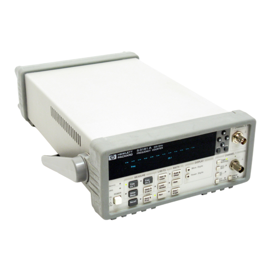
Agilent Technologies 53181A Assembly Level Service Manual (252 pages)
225 MHz Counters
Brand:
Agilent Technologies
| Category:
Cash Counter
| Size: 2.1 MB
Table of Contents
Table of Contents
7
Preface
17
How to Use this Guide
17
Repair Strategy
17
Instrument Identification
17
Instruments Covered by this Guide
18
Assembly-Level Service Guide Organization
18
How to Order Guides
19
Description of the 225 Mhz Counters
20
Options
22
Hardware
22
Support
23
Accessories Supplied and Available
23
Accessories Supplied
23
Accessories Available
23
Performance Tests
25
Introduction
26
Operational Verification
26
Complete Performance Tests
27
Optional GPIB Verification
27
Recommended Calibration Cycle
27
Test Record
27
Equipment Required
28
Agilent 53131A/132A/181A Operational Verification
29
Power-On Self Tests
29
Run Self Test
32
Termination Check
32
External Arm Test (Agilent 53131A/132A Only)
34
Equipment
34
Counter Setup
34
Procedure
35
External Timebase Tests
36
Equipment
36
Mhz External Timebase Input
37
Mhz External Timebase Input
38
10 Mhz External Timebase Input for the Agilent 53132A
39
Agilent 53131A/132A Complete Performance Tests
40
Test 1: Time Interval (Agilent 53131A/132A Only)
41
Equipment
41
Counter Setup
41
Procedure
42
Test 2: Trigger Level (Agilent 53131A/132A Only)
43
Equipment
43
Counter Setup
43
Procedure
44
Test 3: Channels 1 and 2 Frequency Sensitivity (Agilent 53131A/132A Only)
46
Equipment
46
Counter Setup
46
100 Khz to 100 Mhz Sensitivity for Agilent 53131A/132A
47
100 Mhz to 200 Mhz Sensitivity for Agilent 53131A/132A
49
200 Mhz to 225 Mhz Sensitivity for Agilent 53131A/132A
50
Test 4: Channels 1 and 2 Frequency Accuracy (Agilent 53131A/132A Only)
51
Equipment
51
Counter Setup
51
Procedure
52
Test 5: Option 030/050/124 Channel 3 Frequency Sensitivity
54
53131A/132A Only)
54
Equipment
54
Counter Setup
54
100 Mhz to 2.5 Ghz Sensitivity for Agilent 53131A/132A Option
55
030 Only
55
2.7 to 3.0 Ghz Sensitivity for Option 030 Only
56
200 Mhz to 5.0 Ghz Sensitivity for Agilent 53131A/132A (Option 050 Only)
57
200 Mhz to 12.4 Ghz Sensitivity for Agilent 53131A/132A (Option 124 Only)
58
Test 6: Option 030/050/124 Channel 3 Frequency Accuracy
59
(Agilent 53131A/132A Only)
59
Equipment
59
Counter Setup
59
Procedure
59
Test 7: Peak Volts, Channels 1 and 2 (Agilent 53131A/132A Only)
61
Equipment
61
Counter Setup
61
Volt Peak 1
62
Agilent 53131A/132A GPIB Verification Program (Optional)
64
Agilent 53131A/132A Performance Test Record
65
Agilent 53181A Complete Performance Tests
71
Test 1: Trigger Level (Agilent 53181A Only)
72
Equipment
72
Counter Setup
72
Procedure
73
Test 2: Channel 1 Frequency Sensitivity (Agilent 53181A Only)
75
Equipment
75
Counter Setup
75
100 Khz to 100 Mhz Sensitivity for Agilent 53181A
76
100 Mhz to 200 Mhz Sensitivity for Agilent 53181A
78
200 Mhz to 225 Mhz Sensitivity for Agilent 53181A
78
Test 3: Channel 1 Frequency Accuracy (Agilent 53181A Only)
79
Equipment
79
Counter Setup
79
Procedure
80
Test 4: Option 015/030/050/124 Channel 2 Frequency Sensitivity
82
Equipment
82
Counter Setup
82
100 Mhz to 1.5 Ghz Sensitivity for Option 015 Only
83
100 Mhz to 2.7 Ghz Sensitivity for Option 030 Only
84
2.8 to 3.0 Ghz Sensitivity for Option 030 Only
85
200 Mhz to 5.0 Ghz Sensitivity for Option 050 Only
85
200 Mhz to 12.4 Ghz Sensitivity for Option 124 Only
86
Test 5: Option 015/030/050/124 Channel 2 Frequency Accuracy (Agilent 53181A Only)
87
100 Mhz to 1.5 Ghz Accuracy Test for Option 015
87
Equipment
87
Counter Setup
87
Procedure
88
Minimum to Maximum Accuracy Test for Options 030/050/124
89
Test 5: Option 015/030/050/124 Channel
89
Agilent 8663A Synthesized Signal Generator
89
Agilent 8340B Sweep Oscillator
89
Agilent 1250-0780 Type N-To-BNC Connector
89
Agilent 10503A BNC Cable
92
Agilent 10100C 50Ω Feedthrough
92
To Remove the Cover
154
To Remove the Front Bezel
156
To Remove A1 Motherboard Assembly
159
To Remove the A2 Display Board, Keypads, and Window
161
To Remove A3 1.5/3.0/5.0/12.4 Ghz Channel Assembly
163
To Remove A4 AC Power Supply Assembly
165
To Remove A5 DC Power Input Assembly (Option 002)
167
To Remove A6 High Stability Timebase Assembly
169
To Remove the Rear Terminals (Option 060)
171
Ns to
230
Lsd
230
RMS Resolution
230
T Res
230
Results Range:
230
Rat
230
Start Trigger Error
230
Stop Trigger Error
230
Advertisement
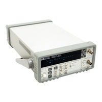
Agilent Technologies 53181A Operating Manual (166 pages)
225 MHz Frequency Counter
Brand:
Agilent Technologies
| Category:
Cash Counter
| Size: 1.91 MB
Table of Contents
Table of Contents
7
In this Guide
16
Contents and Organization
16
Related Documents
17
Types of Service Available if Your Instrument Fails
18
Standard Repair Services (Worldwide)
18
Express Repair/Performance Calibration Service (USA Only)
18
Repair Instrument Yourself
18
Repackaging for Shipment
19
Description of the 225 Mhz Frequency Counter
20
Options
21
Hardware
21
Support
21
Accessories Supplied and Available
22
Accessories Supplied
22
Accessories Available
22
Agilent 53181A Quick Reference Guide
23
1 Getting Started the Front Panel at a Glance
34
The Front Panel Indicators at a Glance
35
The Front Panel Indicators at a Glance (Cont.)
36
The Front Panel Menus at a Glance
37
The Front Panel Menus at a Glance (Cont.)
38
The Display Annunciators at a Glance
40
The Display Special Characters at a Glance
41
The Underscore Placeholder
41
The Asterisk Placeholder
41
The Limit Test Graph Characters at a Glance
42
The Rear Panel at a Glance
43
Making Measurements
44
To Measure Frequency
46
To Select Input Coupling and Impedance
47
Selecting Input Coupling
47
Selecting Input Impedance
47
To Set Input Channel Trigger Level/Sensitivity
48
Changing Trigger Mode
48
Modifying Input Trigger Level
49
Selecting Input Trigger Slope
50
Selecting Input Sensitivity
50
Starting the Measurement
51
To Select Scale and Offset
51
Entering the Scale Value
51
Entering the Offset Value
52
Displaying the Math Results
53
Disabling Math
54
To Set Limits of Measurements
55
Setting the Upper Limit
56
Setting the Lower Limit
57
Setting the Counter to Flag and Stop Measuring on Out-Of-Limit Measurements
59
Setting the Counter to Flag on Limits but Continue Measuring
60
Disabling Limit Testing
60
Disabling Math
61
To Perform Statistics on Measurements
61
Selecting the Type of Statistics (Stats)
61
Computing Stats on Filtered Data Only
63
Displaying Stats after Filtering Data of Input Signal
65
Disabling Stats and Math
66
To Control Measurement
67
2 Operating Your Frequency Counter
69
Chapter Summary
70
Where to Find some Key Working Examples
71
How this Counter Works for You
72
Summary of the Measurement Sequence
73
Using the Measurement Control Keys (Run and Stop/Single)
74
Overview of the Measurement Control Keys
74
To Use the Measurement Control Keys
75
Using Entry/Select (Arrow) Keys
77
To Use During Numeric Entry
77
To Use When Sequencing through the Other Meas and Recall Menus
77
To Use During State Changing (ON/OFF, LO/MED/HI, Etc.)
77
To Use on Prompted Help Messages (MATH HELP: NO/YES, PRT HELP: NO/YES)
78
Using the MEASURE Menu Keys
79
Overview of the MEASURE Menus
79
To Measure Frequency
80
To Measure Frequency Ratio (Optional)
81
To Measure Period
81
To Measure Positive/Negative Volt Peaks
82
Using the Gate & External Arm Menu Key
83
Overview of Gate/External Arming Functions
83
TIME Arming
83
AUTO Arming
83
EXTERNAL Arming
83
DIGITS Arming
84
To Use the Gate and External Arm
85
Example Procedure for Gate and External Arm
85
Example Procedure for Changing the Number of Digits of Resolution Displayed for more Precise Measurements
87
Using the MATH Menu Keys
89
Overview of Scale/Offset Math Menu
89
To Use the Scale/Offset Math Menu
90
Example Procedure for Scale Function
90
Example Procedure for Offset Function
91
Example Procedure for Turning off Math Mode
92
Example Procedure for Set Reference Function-Offset from the Last Measurement Value (Seeing Digits Not Visible on the 12-Digit Display)
93
Overview of Statistics (Stats) Menu
94
To Use the Stats Menu for Automatic and Continuous Statistical Analysis
95
Example Procedure for Computing Stats
95
Example Procedure for Easy Viewing of Stats
96
Example Procedure for Filtering Data (Using Limits) During Stats
97
Example Procedure for Configuring SINGLE to Initiate N Measurements
98
Example Procedure for Turning off Stats Mode
98
Using the LIMITS Menu Keys
99
Overview of Limits Menus
99
To Set and Use Automatic Limit Testing
100
Limits Testing Example 1-Flag and Stop Measuring on Limits
100
Limits Testing Example 2-Flag on Limits but Continue Measuring
102
Limits Testing Example 3-Use Analog Graph Display While Adjusting/Aligning Input Signal
102
Limits Testing Example 4-Selecting Filtering Conditions of Stats Computation
104
Limits Testing Example 5-Sending the Limit-Detect Output to
106
Using the DISPLAY Digits Keys
107
Overview of the DISPLAY Digits Keys
107
To Use the DISPLAY Digits Keys
108
Using CHANNEL 1 Input Conditioning Keys
109
Overview of Trigger/Sensitivity Menu
109
To Use the Trigger/Sensitivity Key to Adjust Counter's Trigger Voltage and Sensitivity Levels
112
Overview of Input Conditioning Toggle Keys
115
Using the Save and Recall Menus
116
Overview of Save and Recall Functions
116
To Use the Save Function
117
To Use the Recall Function
118
To Unsave a Measurement Setup
119
Using the Print Menu
120
Overview of the Print Menu
120
To Use the Print Menu
120
Using the Utility Menu
121
Overview of the Utility Menu
121
To Set the GPIB Address
122
Selecting Operating Mode (Talk/Listen, Talk-Only)
122
Setting the GPIB Address
122
To Choose the Timebase Source
123
To Run the Self-Test Routines
124
Overview of the Self-Test Routines
124
Example Procedure for Running the Self Test
125
To Configure the RS-232 Serial Port for Printing
126
Setting the Hardware Pacing
126
Setting the Baud Rate
127
Setting the Parity
127
Setting the Software Pace
127
To Configure the RS-232 Serial Port for Sending Limit-Detect Output
128
To Select the Numerical Convention for the Display
129
To Connect the Counter to a Serial Printer Via the RS-232 Port
129
To Connect the Counter to a Printer Via GPIB
130
To Select the GPIB Talk-Only Mode for Printing
130
Front Panel Display Messages
131
Measurement Result Displays
131
Power-Up/Self Test Messages
132
Menu Messages
133
GPIB Messages
135
Preset Values after Power-Up and *RST
136
Preset Values for Functions Accessible Via Front Panel or GPIB
136
Preset Values for Functions Accessible Via GPIB Only
140
Common Questions
142
Why Is Stats Result Not Available yet
142
Why Won't Printer Work
142
Why DID Counter Stop Measuring
142
Why DID Counter Go to Its Default State after I Set up My
142
Port
142
Counter's Numeric Display Does Not Follow the Numerical Convention for My Country
142
3 Specifications Introduction
144
Instrument Inputs
144
Instrument Inputs (Continued)
145
Time Base
146
Measurement Specifications
147
Measurement Specifications (Continued)
148
Measurement Definitions
157
Advertisement
Related Products
Agilent Technologies 53150A
Agilent Technologies 53152A
Agilent Technologies 53151A
Agilent Technologies 53131A
Agilent Technologies 53132A
Agilent Technologies 53220A
Agilent Technologies 53230A
Agilent Technologies 53210A
Agilent Technologies 53147A
Agilent Technologies 53148A
Agilent Technologies Categories
Measuring Instruments
Laboratory Equipment
Test Equipment
Water Pump
Power Supply
More Agilent Technologies Manuals
Login
Sign In
OR
Sign in with Facebook
Sign in with Google
Upload manual
Upload from disk
Upload from URL