Sign In
Upload
Manuals
Brands
Aeroflex Manuals
Measuring Instruments
3251
Aeroflex 3251 Manuals
Manuals and User Guides for Aeroflex 3251. We have
1
Aeroflex 3251 manual available for free PDF download: Operating Manual
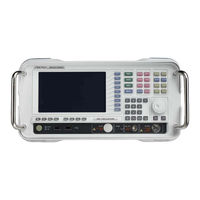
Aeroflex 3251 Operating Manual (228 pages)
SPECTRUM ANALYZERS
Brand:
Aeroflex
| Category:
Measuring Instruments
| Size: 2.37 MB
Table of Contents
Table of Contents
4
Precautions
5
Précautions
8
Vorsichtsmaßnahmen
11
Precauzioni
14
Precauciones
17
General
21
Applications
21
Instrument Configuration
21
Specifications
22
Frequency
22
Amplitude
23
Digitizer
25
AM/FM Demodulation
25
Inputs and Outputs
25
General Specifications
26
Ghz Tracking Generator
27
Preselector- Option 5
28
Versions and Accessories
30
Preparing for Use
32
Installation Site and Environmental Conditions
32
Locations to be Avoided
32
Safety Measures
33
Preparations before Power-On
33
Protective Grounding with Frame Ground Terminal
34
Before Power-On
34
Use a Proper Power Source
34
Do Not Operate with Suspected Damage
34
Object and Liquid Entry
34
Flammable and Explosive Substances
35
Unstable Location
35
Cleaning
35
Replacing Memory Backup Battery
35
Data Storage
35
Altering or Deleting Important Files
35
Input Level to RF Input
36
Front Panel Power Switch
37
Power-On
37
Supply Interruption
37
Detection Mode
38
Introduction
39
Front and Rear Panel Features
40
I/O Connectors
44
GPIB Connector
45
RS-232C Connector
46
Ext VGA Connector
46
USB Connector
47
Ethernet Connector
48
Introduction
49
Screen Layout
71
Selecting Parameters with Touch Screen
72
Toggling Values
72
Control Using Keyboard and Mouse
72
Keyboard
72
Mouse
72
Selecting Spectrum Analysis or Phase Noise Measurement Mode
73
Instrument in Spectrum Analysis Measurement Mode
74
Freq/Span Functions
74
Center-Span Mode Frequency Data Entry
75
Start-Stop Mode Frequency Data Entry
76
Setting Center Frequency Step
77
Setting Frequency Offset
77
Setting 10 Mhz Reference Frequency
77
Setting Signal Tracking
78
Setting Full Span
78
Setting Zero Span
78
Return to the Previous Span
78
Zoom In/Zoom out
79
Amplitude Function
80
Setting Reference Level
80
Setting Input Attenuation
80
Setting Amplitude Scale
81
Selecting Log/Linear Detector Mode
81
Setting Internal Amp
82
Setting MW Amp
82
Setting the Reference Level Offset
82
Setting Amplitude Units
83
Setting Amplitude Correction
84
Selecting Input Impedance
85
Input Attenuator
85
Measurement Function
87
Db down Measurement
87
Adjacent Channel Power Measurement
88
Channel Power Measurement
89
Occupied Bandwidth Measurement
90
Intermodulation (TOI) Measurement
91
Total Power Measurement
92
CCDF Measurement
93
Harmonic Distortion Measurement
93
Spectrum Emission Mask Measurement
94
Spurious Emissions Measurement
95
Average Power Measurement
96
Closing the Window
96
Averaging Measurement
97
Display Function
98
Full Screen
98
Display Line
98
Threshold Line
99
Zoom Display
99
Screen Title
100
White Mode
100
Graticule
100
Annotation
101
Dual Window
101
Text Position
101
Auxiliary Level Display
101
Screen Note Display
101
Trace Function
102
Select Trace
102
Clear&Write
102
Max Hold
102
Min Hold
102
View
103
Blank
103
Trace Array
103
Averaging Function
104
Limit Line Function
105
Drawing a Limit Line
105
Setting the PASS/FAIL Mode
106
Turn off the Limit Line Function
106
Trigger Function
107
Trigger Source
107
Video Trigger
107
External Trigger
107
Selecting Trigger Edge
108
Trigger Delay
108
Coupled Function
109
All Auto
109
Detector Mode
109
Setting Averaging Method
110
Setting FFT & Sweep
111
BW (Bandwidth) Function
112
Auto Bandwidth Function
112
Setting the Resolution Bandwidth
113
Setting the Video Bandwidth
114
Setting the Ratio of VBW and RBW
114
Setting the Ratio of Span and RBW
114
Aux Function
115
AM Demodulation
115
FM Demodulation
115
Audio Monitor
116
Spectrum Display
116
Auto Tune
116
Sweep Function
117
Setting the Sweep Time
117
Continuous Sweep Mode
117
Single Sweep Mode
118
Setting Sweep Time Accuracy
118
Setting the Data Points
118
System Configuration
119
Setting GPIB Address
119
RS-232C Configuration
119
TCP/IP Configuration
120
System Information
120
Preset Function
121
Preset
121
Last State
121
Save/Load User State
122
Boot on
122
Calibration Mode
122
File and Save Function
123
Internal Memory
123
Save Parameters and Waveform
123
File Management
123
Start Key
124
Marker Function
125
Selecting and Changing Marker Position
125
Normal Marker
126
Delta Marker
126
Band Pair
126
Span Pair
127
Marker off in Reverse Order
127
Setting the Marker Trace
127
Delete All Markers
127
Setting the Marker Readout Mode
128
Setting the Marker Table
128
Setting the Marker Name
128
Default Marker Name
128
Marker Averaging Function
128
Setting Parameters Using Marker Values
129
Marker-> Cf/Marker-> Ref
129
Marker-> Start/Marker-> Stop
129
Marker-> Cfstep/Dmarker-> Cfstep
129
Dmarker-> Span
130
Setting Marker Function
130
Peak Search Function
131
Peak Search
131
Next Peak Search
131
Peak Left Search/Peak Right Search
131
Peak to Peak Search
132
Continuous Peak Search
132
Setting the Peak Search Parameters
132
Tracking Generator (Option)
134
Instrument in Phase Noise Measurement Mode
135
Freq/Span Function
135
FREQ Function
135
SPAN Menu
136
AMPL Function
137
Ref.value
137
Scale/DIV
137
Measurement Function
138
MEASURE Menu
138
MEASURE Control Menu
138
Marker Function
140
Select Marker
140
Normal
140
Delta
140
RMS Noise
140
Residual FM
141
Marker Trace
141
Off
141
Marker Table
141
All off
141
Display Function
142
Full Screen
142
Graticule
142
Annotation
142
White Mode
142
Sweep Function
143
Single
143
Continuous
143
Preset Function
144
Introduction
147
Requirement for Performance Tests
147
Instruments Required for Performance Test
148
Test Precautions
149
Frequency Span Readout Accuracy
150
Specification
150
Test Instrument
150
Setup
150
Procedure
151
Reference Oscillator Frequency Stability
153
Specification
153
Test Instruments
153
Setup
153
Procedure
154
Temperature Stability
154
Frequency Counter Accuracy
155
Specification
155
Test Instruments
155
Setup
155
Procedure
156
Resolution Bandwidth (RBW) and Selectivity and Switching Error
157
Resolution Bandwidth (RBW)
157
RBW Accuracy and Selectivity
157
RBW Switching Error
157
Specification
157
Test Instruments
157
Setup
157
Procedure
158
RBW Accuracy
158
RBW Selectivity
161
RBW Switching Error
162
Phase Noise
164
Specification
164
Test Instruments
164
Setup
164
Procedure
165
Residual FM Noise
166
Specification
166
Test Instruments
166
Setup
166
Procedure
167
Average Noise Level
168
Specification
168
Test Instruments
168
Setup
168
Procedure
169
Input Attenuator Switching Error
171
Specification
171
Test Instruments
171
Setup
171
Procedure
172
Frequency Response
175
Specification
175
Test Instruments
175
Setup
175
Procedure
176
Spurious Response
178
Specification
178
Test Instruments
178
Setup
178
Procedure
179
Second Harmonic Distortion
180
Specification
180
Test Instruments
180
Setup
180
Procedure
181
Third-Order Intermodulation
182
Specification
182
Test Instruments
182
Setup
182
Procedure
183
Spurious Relating to Input
184
Specification
184
Test Instruments
184
Setup
184
Procedure
185
Input VSWR
186
Specification
186
Test Instruments
186
Setup
186
Procedure
187
Trigger (EXT, Video, Line)
188
Specification
188
Test Instruments
188
Setup
188
Procedure 1 (EXT Trigger)
188
Procedure 2 (Video Trigger)
189
Preamplifier
190
Specification
190
Test Instruments
190
Setup
190
Procedure
191
Resolving Signals of Equal Amplitude
199
Example: Selection RBW
199
Resolving Small Signals Hidden by Large Signals
201
Example: Selection RBW
201
Making Better Frequency Measurements
203
Example: Marker Counter Function
203
Decreasing the Frequency Span Around the Signal
204
Example: Signal Track Function
204
Tracking Drifting Signals
205
Example 1: Signal Track Function
205
Example 2: Max Hold Function
206
Measuring Low-Level Signals
207
Example 1: Set Input Attenuation
207
Example 2: Selection RBW
209
Example 3: Selection VBW
210
Example 4: Video Average Function
211
Identifying Distortion Products
212
Distortion from the Analyzer
212
Example: Delta Marker Function
212
Third-Order Intermodulation Distortion
213
Example: Delta Marker Function
213
Making Noise Measurements
215
Example 1: MKR Noise Function
215
Example 2: Video Filtering/Average
216
Example 3: Channel Power Measurement
217
Demodulating AM Signals
218
Example: AM Demod. Function
218
Demodulating FM Signals
221
Example 1: Delta Marker Function
221
Example 2: FM Demod. Function
223
Advertisement
Advertisement
Related Products
Aeroflex 3250 Series
Aeroflex 3252
Aeroflex 3253
Aeroflex 3254
Aeroflex 3901
Aeroflex 3920
Aeroflex 3030A
Aeroflex 3035
Aeroflex 3035C
Aeroflex 3036
Aeroflex Categories
Test Equipment
Measuring Instruments
Control Unit
Portable Generator
Marine Radio
More Aeroflex Manuals
Login
Sign In
OR
Sign in with Facebook
Sign in with Google
Upload manual
Upload from disk
Upload from URL