Sign In
Upload
Manuals
Brands
Advantech Manuals
Touch Panel
PPC-125
Advantech PPC-125 Manuals
Manuals and User Guides for Advantech PPC-125. We have
1
Advantech PPC-125 manual available for free PDF download: User Manual
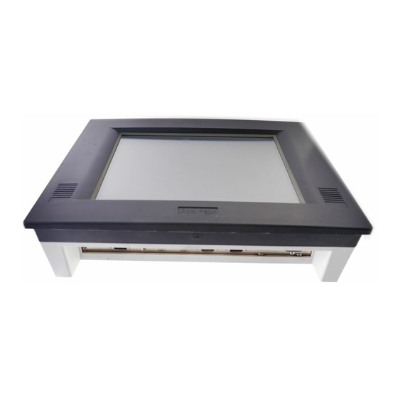
Advantech PPC-125 User Manual (60 pages)
Intel Core 2 Duo Processor-Based Panel PC with 12” Color TFT LCD Display
Brand:
Advantech
| Category:
Touch Panel
| Size: 1.85 MB
Table of Contents
Declaration of Conformity
3
Safety Instructions
4
Table of Contents
7
Chapter 1 General Information
11
Introduction
12
Specifications
12
General Specifications
12
Standard PC Functions
12
Internal Graphics Specification
12
Audio Function
12
Ethernet Interface
13
Touchscreen Specifications (Optional)
13
Table 1.1: Touchscreen Specifications
13
Optional Module
13
Environment
13
Certifications
13
Dimensions
14
Figure 1.1 Dimensions of PPC-125
14
Chapter 2 System Setup
15
A Quick Tour of the Panel PC
16
Figure 2.1 Front Panel of PPC-125
16
Figure 2.2 Side View of the Panel PC
16
Figure 2.3 I/O Peripheral Connectors Panel
17
Figure 2.4 Rear View of the Panel PC
17
Preparing for First-Time Use
18
Installation Procedures
18
Connecting the Power Cord
18
Connecting the Keyboard and Mouse
18
Switching on the Power
18
Running the BIOS Setup Program
18
Installing System Software
19
Installing the Drivers
19
Figure 2.5 Drivers and Utilities on the CD-ROM
19
Chapter 3 Using the Panel PC
21
Introduction
22
CD-ROM Drive (Optional)
22
Figure 3.1 Inserting and Ejecting a CD-ROM
22
PS/2 Mouse and Keyboard
22
PCI or PCI-E Bus Expansion
23
Figure 3.2 PCI & PCI-E Bus Expansion
23
Serial COM Ports
24
Figure 3.3 I/O Ports
24
VGA Port
24
USB Ports
25
Audio Interface
25
Ethernet
25
Touchscreen (Optional)
25
Chapter 4 Hardware Installation
27
Jumpers and Connectors
28
Disassembling the Panel PC
28
Figure 4.1 Unfastening the Rear Cover
28
Figure 4.2 Disconnecting the Fan Connector
29
Figure 4.3 the PPC Without the Rear Cover
29
Installing the 2.5" Hard Disk Drive
30
Figure 4.4 the PPC Side Cover
30
Figure 4.5 the PPC HDD
30
Figure 4.6 the PPC HDD
31
Figure 4.7 Plugging in the SATA Cable
31
Figure 4.8 Fastening the HDD Metal Frame to the HDD
32
Installing the Central Processing Unit (CPU)
32
Figure 4.9 Placing the CPU in the Socket
33
Figure 4.10Tightening the Screws on the CPU
33
Figure 4.11Placing the Heatsink and Fan on the CPU and then Fastening
34
Installing the DDR2 SDRAM Memory Module
34
Figure 4.12Placing the Memory Module in the SODIMM Socket
34
Installing the Optical Device Drive
35
Figure 4.13Rear Cover Photo
35
Figure 4.14Rear Cover Photo with ODD Bracket
35
Figure 4.15Riser Card Installation
36
Figure 4.16Riser Card and ODD Connection
36
Figure 4.17Add-On ODD Cover
37
Chapter 5 Jumpers and Connectors
39
Setting Jumpers
40
Jumpers and Connectors
40
Jumpers
41
Jumper and Connector Locations
42
Figure 5.1 Jumpers & Connectors on PPC-125 Motherboard
42
Connectors
43
Table 5.1: CN1 (USB Port 6)
44
Table 5.2: CN2 (CPU FAN Connector)
44
Table 5.3: CN3 (LVDS2 Connector)
44
Table 5.4: CN4 (LVDS1 Connector)
45
Table 5.5: CN5 (System FAN Connector)
45
Table 5.6: CN8 (SATA HDD Power Connector)
45
Table 5.7: CN9 (SATA HDD Connector)
45
Table 5.8: CN10 (+V12 Power Connector)
46
Table 5.9: CN12 (ATX Power Input Connector)
46
Table 5.10: CN13 (USB Port 4/5)
46
Table 5.11: CN15 (SPI Reflash Connector)
46
Table 5.12: CN17 (SATA ODD Connector)
47
Table 5.13: CN18 (SATA ODD Power Connector)
47
Table 5.14: CN19 (Multi Function PCI Express By1 Connector)
47
Table 5.15: CN21 (Printer Port Connector)
48
Table 5.16: CN22 (LCD Light Sense Connector)
48
Table 5.17: CN24 (COM4 Connector)
48
Table 5.18: CN25 (Front Panel LED Connector)
48
Table 5.19: CN26 (COM1 RI Function Selection Connector)
49
Table 5.20: CN28 (LCD Back Light Connector)
49
Table 5.21: CN29 (Power Button Connector)
49
Table 5.22: CN34A (COM3 RS-232 Serial Port)
49
Table 5.23: CN34B (VGA)
49
Table 5.24: CN35 (Internal Speaker Connector)
50
Table 5.25: CN36 a (COM1 RS232)
50
Table 5.26: CN36 B (COM2 RS232/422/485 Select by BIOS)
50
Table 5.27: CN37 (MINIDIN PS2 Connector)
51
Table 5.28: CN41 (Clear CMOS Connector (Reserved))
51
Table 5.29: CN42 (COM3 RI Function Selection Connector)
51
Table 5.30: CN43 (COM4 RI Function Selection Connector)
51
Table 5.31: CN44 (COM2 RI Function Selection Connector)
51
Table 5.32: CN45 (at Power Solution Connector)
52
Table 5.33: CN47 (GPIO)
52
Jumper Settings
52
Table 5.34: CN26 (COM1 RI Function Selection Connector
52
Table 5.35: CN41 (Clear CMOS (Reserved))
52
Table 5.36: CN42 (COM3 RI Function Selection Connector
52
Table 5.37: CN43 (COM4 RI Function Selection Connector)
52
Table 5.38: CN44 (COM2 RI Function Selection Connector)
53
Table 5.39: CN45 (at Power Selection)
53
Chapter 6 Driver Installation
55
Introduction
56
Driver Installation
56
Updating Driver Search on the Advantech Website
56
Appendix Apci Card and PCI-E Size Limits
57
PCI Interface Card
58
PCI-E Interface Card
58
Advertisement
Advertisement
Related Products
Advantech PPC-120
Advantech PPC-175T
Advantech PPC-154
Advantech PPC-155T
Advantech PPC-140
Advantech PPC-150 Series
Advantech PPC-157T
Advantech PPC-177T
Advantech PPC-153
Advantech PPC-103
Advantech Categories
Motherboard
Computer Hardware
Desktop
Touch Panel
Network Router
More Advantech Manuals
Login
Sign In
OR
Sign in with Facebook
Sign in with Google
Upload manual
Upload from disk
Upload from URL