Sign In
Upload
Manuals
Brands
Advance acoustic Manuals
Floor Machine
56514926
Advance acoustic 56514926 Manuals
Manuals and User Guides for Advance acoustic 56514926. We have
2
Advance acoustic 56514926 manuals available for free PDF download: Service Manual, Instructions For Use Manual
Advance acoustic 56514926 Service Manual (260 pages)
Nilfisk CR1500; 56514850; 56514852; 56514854
Brand:
Advance acoustic
| Category:
Ultrasonic Jewelry Cleaner
| Size: 14 MB
Table of Contents
Table of Contents
2
General Information
9
General Machine Description
9
Machine Configurations
9
Hydraulic System
9
Drive and Steering Systems
9
Solution System
10
Scrub System
10
Squeegee System
10
Recovery System
10
Main Sweep System
11
Side Sweep System (Optional)
11
Dust Control System (Variable Dump Models Only)
11
Service Manual Purpose and Application
11
Other Reference Manuals and Information Sources
12
Nilfisk-Advance Publications
12
Engine Manufacturers' Technical Manuals
12
Diagnostic and Service Tools
13
Conventions
15
Parts and Service
15
Nameplate
15
Cautions and Warning Symbols
16
General Safety Instructions
16
Hopper Safety Lock Arm (Variable Dump Only)
18
Jacking the Machine
19
Transporting the Machine
19
Towing or Pushing the Machine
20
Technical Specifications
22
General Specifications
22
Overall Dimensions
23
Engine and Machine Performance
24
Fastener Torque Specifications
24
Maintenance
24
Recommended Service Materials
25
Maintenance Schedules
25
Daily Maintenance
25
Weekly Maintenance/Every 50 Hours
26
Maintenance Every 100 Hours
26
Maintenance Every 200 Hours
27
Maintenance Every 250 Hours
27
Maintenance Every 400 Hours
27
Maintenance Item Locations
28
Lubrication Locations
29
Lubrication Every 100 Hours
29
Lubrication Every 250 Hours
29
General Machine Overview
32
Major Machine Components
32
Machine Controls
33
Engine Controls
33
Gauges and Meters
34
Solution Control and Indicator
34
Esp/Recycle Option Controls and Indicators
35
Scrub System Controls
35
Squeegee and Recovery System Controls
36
Main Broom Controls
37
Side Broom Controls
38
Hopper Controls (Variable Dump Models)
39
Dust Control and Filter Shaker Controls (Variable Dump Models)
40
Miscellaneous Controls
40
Dust Control System
42
Dust Control System.
42
Functional Description
42
Overview
42
Filter Assembly
43
Dust Control Vacuum Fan Motor Assembly
43
Dust Control Motor Valves
44
Dust Control System Wiring Diagram
45
Electrical Circuit Description
45
Shaker Motor Nominal Conditions
45
Dust Control System Hydraulic Diagrams
46
Main Broom and Dust Control Motors off
46
Main Broom and Dust Control Motors on
47
Main Broom Motor on and Dust Control Motor off (with Wet Sweep Bypass Option)
48
Component Locations
49
Dust Control Filter Maintenance
52
Troubleshooting
55
Specifications
56
Electrical System
57
Functional Description
57
Overview
57
Instrument Panel and Circuit Breakers
57
Foot Pedal Proximity Switches
58
Electrical Ladder Diagrams
59
Electrical Ladder Diagram, P/N 56382653, Rev. B
59
Electrical Ladder Diagram, P/N 56382653, Rev. B
61
Electrical Ladder Diagram, P/N 56382653, Rev. B
62
Engine Harness - GM 3.0L Gas, P/N 56380222
71
Engine Harness -GM 3.0L LPG, P/N 56380221
72
Machine Harness Routing Diagram - Gas, LP and Diesel
73
Engine System (Common)
74
Engine Frame Side System - Mitsubishi Diesel
75
Engine Frame Side System - GM Gas
76
Engine Frame Side System - GM LPG
77
Scrub System Electrical System
78
Shaker Motor and Hopper Electrical System
79
Squeegee and Vacuum Fan Motor Electrical System
80
Component Locations
82
Battery
82
Relays
82
Instrument Panel
83
Circuit Breakers
83
Foot Pedal Proximity Switches
84
Troubleshooting
84
Specifications
84
Component Specifications
84
Engine System, Diesel
85
Functional Description
85
Overview
85
Diesel Engine Wiring Diagram
85
Circuit Description
86
Component Locations
86
Maintenance and Adjustments
90
Engine Coolant
90
Checking Engine Coolant
90
Replacing Engine Coolant
91
Engine Air Filter Maintenance
92
Troubleshooting
92
General Troubleshooting
92
Engine Overheating Problems
93
Loss of Oil Pressure Protection
94
Specifications
94
Special Tools
95
Engine System, Gasoline/Lpg
96
Functional Description
96
Overview
96
GM Engine Wiring Diagram
96
Circuit Description
97
GM 3.0L Gasoline Fuel System Description
97
GM 3.0L LPG Fuel System Description
97
Component Locations
98
LPG and Gasoline
98
Lpg
102
Gasoline
104
Firing Order and Plug Wire Routing
105
Maintenance and Adjustments
105
Engine Oil
105
Engine Coolant
106
Checking Engine Coolant
106
Replacing Engine Coolant
106
Engine Air Filter Maintenance
107
Troubleshooting
108
General Troubleshooting
108
Engine Overheating Problems
108
Loss of Oil Pressure Protection
109
Engine Diagnostics
109
To Access the Engine Diagnostic Information Using the Controller Interface Kit and a PC
109
To Access the Engine DTC Error Codes Manually
111
Diagnostic Trouble Code (DTC) Chart - Sorted by DTC Number
112
Specifications
116
Engine Specifications
116
Special Tools
117
Hopper System
118
Functional Description
118
Overview
118
Hopper - Manual Dump Machines
118
Hopper - Variable Dump Machines
119
Hopper System Wiring Diagram - Variable Dump Machine
121
Electrical Circuit Description - Variable Dump Machine
121
Hopper System Hydraulic Diagrams - Variable Dump Machine
122
Hopper Control Valves in Neutral Position
122
Lift Hopper
123
Lower Hopper
124
Open Hopper Dump Door
125
Close Hopper Dump Door
126
Component Locations
127
Lubrication Points
128
Troubleshooting
131
Hydraulic System
132
Functional Description
132
Overview
132
Hydraulic Pumps
132
Hydraulic Valves
133
Return Block/Manifold
134
Electrical Schematic
135
Electrical Circuit Description
135
Hydraulic Schematics
136
Variable Dump Machine
136
Manual Dump Machine
137
Component Locations
138
Maintenance and Adjustments
142
Hydraulic Oil Level
142
Hydraulic Oil Filter
142
Troubleshooting
143
General Troubleshooting
143
General Information Regarding Checking Hydraulic Pressures
143
Checking Nominal Pressure Readings
144
Specifications
145
General Specifications
145
Scrub Deck Hydraulic Specifications
146
Transport Circuit Hydraulic Specifications
146
Steering Circuit Hydraulic Specifications
147
Side Broom Hydraulic Specifications - GM and Mitsubishi Engines
147
Main Broom Hydraulic Specifications - GM Engines
148
Main Broom Hydraulic Specifications - Mitsubishi Engines
148
Dust Control System Hydraulic Specifications - GM Engines (Variable Dump Models)
149
Dust Control System Hydraulic Specifications - Mitsubishi Engines (Variable Dump Models)
149
Squeegee System Hydraulic Specifications - GM Engines
150
Squeegee System Hydraulic Specifications - Mitsubishi Engines
150
Main Control Valve Specifications
151
Cylinder Control Valve Specifications
152
Special Tools
153
Recovery System
154
Functional Description
154
Overview
154
Recovery Tank - Standard Recovery System
154
Recovery Tank - Esp/Recycle System
155
Vacuum Motor/Fan Assembly
156
Recovery System Wiring Diagram - Standard Recovery System
157
Electrical Circuit Description - Standard Recovery System
157
Recovery System Hydraulic Diagrams
158
Squeegee Vacuum Fan off
158
Squeegee Vacuum Fan on
158
Squeegee Vacuum Fan Stalled
159
Component Locations
160
Recovery Tank
160
Maintenance
163
Daily Maintenance
163
Recovery Tank
163
Troubleshooting
163
Vacuum Test
164
Specifications
165
Special Tools
165
Scrub System
166
Functional Description
166
Overview
166
Scrub Deck
166
Scrub Brush Motor Control Valves
167
Scrub Deck Hydraulic Cylinder and Control Valves
168
Scrub System Wiring Diagram
169
Circuit Descriptions
169
Scrub Brush Motors
169
Scrub Deck Cylinder
170
Scrub System Hydraulic Diagrams
170
Scrub Brush Motors on
173
Scrub Brush Motors Running in Reverse
175
Scrub Deck down at Normal Scrub Pressure
176
Scrub Deck down at High Scrub Pressure
177
Scrub Deck up
178
Scrub Deck up with Engine Shut off
179
Component Locations
180
Troubleshooting
182
Specifications
184
Component Specifications
184
Special Tools
185
Solution System
186
Functional Description
186
Overview - Standard Solution System
186
Solution Tank
187
Solution Flow Control
188
Overview - Esp/Recycle Option
189
Detergent and Solution Tanks
190
Detergent Pump
190
Solution off in Neutral Option
191
Power Spray Wand (Optional)
192
Standard Solution System Wiring Diagram
193
Circuit Description
193
Esp/Recycle Option Wiring Diagram
194
Circuit Description
194
Component Locations
195
Standard Solution System
195
Esp/Recycle Option
198
Maintenance
200
Solution Tank
200
Detergent System (Esp/Recycle Option Only)
200
Troubleshooting
200
Specifications
202
Component Specifications
202
Solution System
202
ESP Detergent System
202
Squeegee System
203
Squeegee System.
203
Functional Description
203
Overview
203
Rear Squeegee Assembly
203
Swing Squeegee Support
204
Squeegee Lift Assembly and Squeegee Deck Cylinder
205
Squeegee Deck Cylinder and Control Valves
206
Squeegee System Wiring Diagram
207
Circuit Description
207
Squeegee System Hydraulic Diagrams
208
Squeegee Up, Key Switch off
208
Squeegee Up, Engine Running
209
Squeegee Down, Engine Running
210
Component Locations
211
Troubleshooting
213
General Troubleshooting
213
Specifications
214
Steering System
215
Functional Description
215
Overview
215
Hydraulic Diagrams
217
Power Steering Unit Description
217
Steering Wheel Stationary
217
Steering Wheel Turned Toward the Right
218
Steering Wheel Turned Toward the Left
219
Steering Wheel Held in Full Right or Left Position
220
Turning the Steering Wheel with the Engine off
221
Maintenance
222
Troubleshooting
223
Removal and Installation
223
Specifications
223
Sweep System, Main Broom
224
Functional Description
224
Overview
224
Main Broom and Broom Drive Motor
224
Main Broom Lift Linkage
225
Main Broom Motor Control Valve
226
Main Broom Sweep System Wiring Diagram
227
Circuit Description
227
Main Broom Sweep System Hydraulic Diagrams
227
Main Broom Motor off
228
Main Broom Motor on
229
Component Locations
230
Maintenance and Adjustments
233
Sweep System, Side Broom
235
Functional Description
235
Overview
235
Side Broom Sweep System Wiring Diagram
236
Circuit Description
236
Side Broom Sweep System Hydraulic Diagrams
237
Side Broom Motor off
237
Side Broom Motor on
238
Component Locations
239
Maintenance and Adjustments
240
To Adjust the Side Broom Height
240
Troubleshooting
241
General Troubleshooting
241
Specifications
241
Wheel System, Non-Traction
242
Functional Description
242
Maintenance and Adjustments
244
Service Brake Adjustment
244
Parking Brake Adjustment
244
Troubleshooting
245
Specifications
245
Wheel System, Traction
246
Functional Description
246
Overview
246
Drive Pump
246
Drive Pump before Machine Serial Number 1000034942
246
Drive Pump after Machine Serial Number 1000034942
247
Forward/Reverse Controls
247
Forward/Reverse Controls - GM Engines before S/N 1000034942
248
Forward/Reverse Controls - GM Engines after S/N 1000034942
248
Foot Pedal Assembly - GM Engines
249
Forward/Reverse Controls - Mitsubishi Diesel Engines before S/N 1000034942
250
Forward/Reverse Controls - Mitsubishi Diesel Engines after S/N 1000034942
251
Rear Wheel and Rear Wheel Motor
252
Electrical Schematic
253
Electrical Circuit Description
253
Hydraulic Diagrams
254
Rear Wheel Motor in Neutral
254
Tow Valve in Bypass Position
255
Rear Wheel Motor in Forward or Reverse
256
Rear Wheel Motor Stalling out
257
Maintenance and Adjustments
258
Lubrication
258
Hydroback Adjustment
258
Troubleshooting
259
Specifications
259
Component Specifications
259
Wheel Drive System Torque Specifications
260
Advertisement
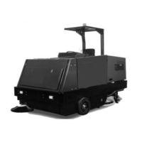
Advance acoustic 56514926 Instructions For Use Manual (80 pages)
Floor Sweeper & Washer
Brand:
Advance acoustic
| Category:
Floor Machine
| Size: 1 MB
Table of Contents
Français
3
Table of Contents
2
Table of Contents
3
Introduction
4
Parts and Service
4
Nameplate
4
Machine Operation
5
Preparing the Machine for Operation
5
Cautions and Warnings
6
Consignes de Prudence Et de Securite
7
Operation of Controls and Gauges
8
Ignition Switch
8
Light Switch
8
Turn Signal (Option
9
Glow Plug Switch
9
Horn Push Button
9
Side Broom Lift
9
Main Broom Switch
10
Side Broom Switch
10
Dust Control Switch
10
Filter Shaker Switch
10
Water Temperature Gauge
11
Hour Meter
11
Fuel Gauge
11
Oil Pressure Gauge
11
Volt Meter
11
Scrub Brushes Switch
12
Brush Rotation Switch
12
Brush Pressure Switch
12
Squeegee Blade Switch
12
High Recovery Warning Light
12
Low Solution Warning Light
12
Hopper Lift
13
Hopper Safety Lock Arm
13
Hopper Dump Door
13
Manual Dump Hopper
13
Solution Control
13
Sweeping Broom Lift Control
13
Throttle
14
Check Engine Light
14
Parking Brake
14
Foot Brake
14
Accelerator & Directional Control Pedal
15
Backup Alarm Switch
15
Seat Adjustment
15
Scrubbing System Operating Instructions
16
ESP Recycling Control Panel
16
ESP Recycling System On/Off Switch
16
Solution High Warning Light
16
Detergent Low Warning Light
16
Detergent Flow Knob
16
The Scrubbing System - How It Works
17
Dust Control Operating Instructions
19
Operating Instructions
20
Filling the Solution Tank - ESP
20
Pre-Start Checklist
20
Before Starting the Engine
20
Post-Start Checklist
21
Helpful Hints for Cleaning Operation
22
Post-Operation & Clean-Up Instructions
23
To Stop the Cleaning Operation
23
Post-Operation Checklist
23
To Drain the Solution Tank
23
To Clean the Solution Tank
23
To Drain the Recovery Tank
23
To Clean the Recovery Tank
24
To Empty the Debris Hopper
25
Towing Instructions
25
Service Chart
26
General Machine Maintenance
28
Lubrication
28
Engine
29
Main Broom Level Adjustment
30
Side Broom Level Adjustment
30
Side Broom Replacement
30
Flaps
31
Scrub Brush Replacement
32
Covers and Latches
32
Solution Warning Light
32
Recovery Warning Light
32
Solution Control - ESP
32
Recycling Pump ESP System
33
Rear Squeegee
33
Squeegee Caster Wheels
33
Adjusting Casters
33
General Troubleshooting
34
Español
38
Índice
39
Introducción
40
Componentes y Servicio
40
Placa de Identifi Cación
40
Desembalaje
40
Funcionamiento de la Máquina
41
Preparación de la Máquina para Su Uso
41
Precauciones y Advertencias
42
Instrucciones Generales de Seguridad
42
Interruptor de Encendido
44
Interruptor de Iluminación
44
Intermitente de Giro (Opcional
45
Interruptor de Bujía de Calentamiento
45
Botón Pulsador del Claxon
45
Elevación del Cepillo Lateral
45
Interruptor del Cepillo Principal
46
Interruptor del Cepillo Lateral
46
Interruptor de Control del Polvo
46
Interruptor del Agitador del Fi Ltro
46
Indicador de Temperatura del Agua
47
Medidor de Horas de Funcionamiento
47
Indicador de Combustible
47
Manómetro del Aceite
47
Voltímetro
47
Interruptor de Cepillos de Fregado
48
Interruptor de Rotación de Los Cepillos
48
Interruptor de Presión de Los Cepillos
48
Interruptor de la Hoja de la Rasqueta
48
Luz de Advertencia de Mucha Recuperación
48
Luz de Advertencia de Poca Solución
48
Elevación de la Tolva
49
Brazo de Fi Jación de Seguridad de la Tolva
49
Puerta de Descarga de la Tolva
49
Tolva de Descarga Manual
49
Control de la Solución
49
Control de Elevación del Cepillo de Barrido
49
Luz de Comprobación del Motor
50
Freno de Estacionamiento
50
Freno de Pedal
50
Pedal Acelerador y de Control Direccional
51
Interruptor de Alarma de Marcha atrás
51
Ajuste del Asiento
51
Instrucciones de Uso del Sistema de Fregado
52
Interruptor de Encendido/Apagado del Sistema de Reciclaje ESP
52
Luz de Advertencia de Mucha Solución
52
Luz de Advertencia Poco Detergente
52
Botón de Fl Ujo de Detergente
52
El Sistema de Fregado: Cómo Funciona
53
Sistema de Fregado con Recuperación O ESP: Cómo Funciona
54
Instrucciones de Uso del Control del Polvo
55
Instrucciones de Uso
56
Llenado del Depósito de la Solución: ESP
56
Lista de Comprobación Previa a la Puesta en Marcha
56
Antes de Poner en Marcha el Motor
56
Lista de Comprobación Posterior a la Puesta en Marcha
57
Consejos Útiles para la Operación de Limpieza
58
Instrucciones tras el Funcionamiento y para Limpieza
59
Para Detener la Operación de Limpieza
59
Lista de Comprobación tras el Funcionamiento
59
Para Vaciar el Depósito de la Solución
59
Para Limpiar el Depósito de la Solución
59
Para Vaciar el Depósito de Recuperación
59
Para Limpiar el Depósito de Recuperación
60
Para Vaciar la Tolva de Residuos
61
Instrucciones Remolque
61
Tabla de Mantenimiento
62
Mantenimiento General de la Máquina
64
Lubricación
64
Motor
65
Ajuste del Nivel del Cepillo Principal
66
Ajuste del Nivel del Cepillo Lateral
66
Sustitución del Cepillo Lateral
66
Aletas
67
Sustitución del Cepillo de Fregado
68
Cubiertas y Seguros
68
Luz de Advertencia de la Solución
68
Luz de Advertencia de Recuperación
68
Control de la Solución: ESP
68
Sistema ESP de Bomba de Reciclaje
69
Rasqueta Trasera
69
Ruedas Pivotantes de las Rasquetas
69
Ajuste de las Ruedas Pivotantes
69
Resolución de Problemas Generales
70
Advertisement
Related Products
Advance acoustic 56514925
Advance acoustic 56514927
Advance acoustic 56514928
Advance acoustic 56514929
Advance acoustic 56514930
Advance acoustic 56514931
Advance acoustic 56511711
Advance 56511810
Advance 56511811
Advance 56511812
Advance acoustic Categories
Aircrafts
Floor Machine
Amplifier
Scrubber
Accessories
More Advance acoustic Manuals
Login
Sign In
OR
Sign in with Facebook
Sign in with Google
Upload manual
Upload from disk
Upload from URL