Sign In
Upload
Manuals
Brands
ADPRO Manuals
DVR
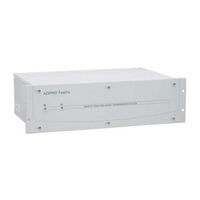
FastTrace AFT-5010-*-*-D
ADPRO FastTrace AFT-5010-*-*-D Manuals
Manuals and User Guides for ADPRO FastTrace AFT-5010-*-*-D. We have
1
ADPRO FastTrace AFT-5010-*-*-D manual available for free PDF download: Installation And User Manual
ADPRO FastTrace AFT-5010-*-*-D Installation And User Manual (146 pages)
Multi-Site Video Security System
Brand:
ADPRO
| Category:
DVR
| Size: 2 MB
Table of Contents
User Manual
1
Document Conventions
3
Fcc Compliance Statement
3
Radio Interference
4
Declaration of Conformity
6
Table of Contents
7
1 Introduction
13
Figure 1: Typical Application
14
2 Fasttrace Setup Instructions
15
Physical Location
15
General Power Requirements
15
Power Conditioners and Surge Arresters
16
Interference Caused by Ground Loops
16
System Wiring Considerations
16
Electromagnetic Compatibility (EMC) Issues and Instructions
16
Static Discharge
17
Grounding Requirements
17
Unpacking the Fasttrace
18
Figure 2: Fasttrace Grounding Requirements
18
Mounting the Fasttrace
19
Rack Mounting
19
Setting the Video Standard
19
Figure 3: Fasttrace Front Panel for 19 Inch Rack Mount Models
19
Setting up the PC
20
Logging Onto Windows
20
Removing Previous Versions of Software
20
Figure 4: Typical Setup Connections - Ethernet or Serial
20
Configuring the PC for Ethernet Connection
21
Figure 5: Internet Protocol
21
Configuring the PC for Serial Connection
22
Figure 6: System Properties
22
Figure 7: Device Manager
22
Figure 8: COM Port Settings
23
Installing the Null Modem Driver
23
Figure 10: Install New Modem
24
Figure 9: Phone and Modem Options
24
Figure 11: Select Modem Driver from Disk
25
Figure 12: Install from Disk
25
Figure 13: Select Modem COM Port
26
Figure 14: Installation Warning
26
Null-Modem Cable Wiring
27
Installing Videocentral Lite Software
27
Figure 15: Null-Modem Wiring
27
Figure 16: Installation Screen
27
Figure 17: Setup Wizard Introduction Screen
28
Figure 18: Installation Location
28
Figure 19: Transmitter Alarm Management
29
Figure 20: Communication Devices
29
Starting Videocentral Lite for the First Time
30
Figure 21: Setup Complete
30
Figure 22: Dongle Required
30
Fasttrace Configuration
31
Figure 23: Default Ethernet Site Configuration
31
Figure 24: Default Serial Site Configuration
31
Powering up the Fasttrace
32
Connecting to the Fasttrace for the First Time
32
Figure 25: Connect to Site
33
Figure 26: Videocentral User Interface
33
Figure 27: Installer Menu Button
34
Adding a New Site
35
Figure 28: Fasttrace User Settings
35
Testing the Fasttrace Installation
36
Figure 29: Configure a New Site
36
Figure 30: Camera List
36
Notes and Troubleshooting Tips
37
Setting the Date and Time
37
Front Panel LED
37
Fasttrace Connection Details Lost
37
Firewall Configuration
38
Table 1: Firewall Ports
38
3 Fasttrace Connectors
39
Figure 31: Fasttrace Connections
39
Power Connection
40
Connecting Communication Devices
40
Comms 1
40
Figure 32: Comm1 Pin Numbers
40
Table 2: Comm Port 1 Connection
40
Comms 2
41
Table 3: Comm Port 2 Connection
41
Connecting to a Modem or TA
42
Figure 33: Modem Connection
42
Network (Ethernet) Connection
42
Table 4: Ethernet Connection
42
Audio
43
Audio Switch Port
43
Figure 34: Audio D-Connector Pinouts
43
Audio Screw Terminal Connector
44
Figure 35: Audio Connector Pinouts
44
Table 5: Audio Switcher Connections
44
Audio Configuration
45
Figure 36: Audio Configuration with Amplifier
45
Table 6: Audio Screw Terminal Connector
45
Figure 37: Microphone Connection
46
Figure 38: Fasttrace with Intercom
46
Zoned Audio
46
Video Input Connections
47
Figure 39: Zoned Audio Configuration
47
Figure 40: Video Configuration
48
Video Input Requirements
48
Maximum Camera Input Cable Length
49
Video Output
49
Configuration Switches
49
Figure 41: Video Output Configuration
49
Table 7: DIP Switch Configuration
50
Alarm Inputs
51
Driving the Alarm Inputs
52
Figure 42: Alarm Input Configuration
52
Figure 43: Alarm Connector Pinouts
53
Control Outputs
54
Figure 44: External Sensor Wiring Circuits
54
Connecting to the Control Outputs
55
PTZ Connection
55
Figure 45: Pinouts for Control Output Connectors
55
Figure 46: External Relay - Typical Output Circuit
55
Figure 47: Pin Numbering of the PTZ Port
56
Figure 48: Typical RS485 Connection to Multiple Telemetry Stations
56
Table 8: PTZ Port Connections
56
Figure 49: Typical PTZ Configuration
57
PTZ Port Setup
57
General Purpose Serial Ports
58
Figure 50: RS485 PTZ Port Connections to a Telemetry Station
58
Figure 51: Pin Numbering of the Serial Port
58
Data Connection
59
Figure 52: Typical Configuration with ATM/EPOS
59
Table 9: General Purpose Serial Port Connections
59
Connecting to the General I/O
60
Export Evidence - Pin 1
60
Figure 53: Pin Numbering of the Data Port
60
Figure 54: Pinouts for General I/O Connector
60
Table 10: Data Port Connections
60
Access/Secure Input - Pin 3
61
Clock Synchronise - Pin 5
61
Fault Relay
61
Mode Select Input - Pin 9
61
Push to Talk - Pin 7
61
General Alarm Relay Output
62
Powering up the Fasttrace
62
4 Programming Fasttrace
63
Programming Checklist
63
Setting the Operational Parameters
63
Setting the Network Connection
63
Setting the Telephone Connection
64
Entering the Fasttrace Setup Screen
64
Figure 55: Installer Menu Icon
64
Figure 56: Fasttrace User Settings
65
Figure 57: TCP IP Settings
66
Figure 58: Incompatible User Settings File
66
Loading a Configuration from File
66
Saving a Configuration to File
66
Site Details
67
Figure 59: Site Details Menu
67
Passwords
67
Site ID
67
Date/Time Settings
68
Figure 60: Date/Time Settings Menu
68
Figure 61: Set Fasttrace Time and Date
69
Table 11: Time Change Compatibility Matrix
69
Figure 62: Licensing Settings
71
Licensing
71
Communications
72
Ethernet Properties
72
Figure 63: Communications Menu
72
Figure 64: Ethernet Settings
73
Figure 65: Serial Communication Port Settings Menu
75
Serial Communication Properties
75
Figure 66: Advanced Serial Communications
78
Advanced Communication Properties
79
Figure 67: Advanced Communication Properties
79
Call List
81
Figure 68: Call List Menu
81
Main Communications Link
81
Backup Communications
82
Figure 69: Call List (Ethernet-Left, Serial-Right) Properties
82
Connected Equipment
83
Figure 70: Connected Equipment Menu
83
General Alarm Relay Settings
83
PTZ Settings
84
Cameras
84
Camera Settings
85
Figure 71: Cameras Menu
85
Figure 72: Camera Settings - General Tab
86
Figure 73: Camera Settings - PTZ
87
Figure 74: Alarm Preset Warning
88
Figure 75: Camera Settings - Activity Detection Tab
89
Figure 76: Activity Detection Mask
90
Figure 77: Monitor Menu
91
Monitor
91
Monitor Settings
91
Transaction Devices
91
Figure 78: Transparent Data Port Menu
92
Transparent Data Port
92
Figure 79: Transparent Data Port Settings
93
Alarm Inputs
94
Alarm Input Settings
94
Figure 80: Unallocated Icon
94
Figure 81: Alarm Contacts List
94
Presidium Inputs
96
Figure 82: Unallocated Icon
96
Figure 83: Presidium Inputs List
97
Figure 84: Presidium Input Settings
97
Presidium Input Settings
97
Control Outputs
98
Figure 85: Control Output Settings Menu
98
Control Output Settings
99
Audio
99
Audio General Properties
100
Figure 86: Audio Settings
100
Arming / Disarming
101
Alternative Arm/Disarm Input
101
Figure 87: Arming/Disarming Menu
101
Indicate Active Sensor
102
Indicate the Armed State of the Unit
102
Table 12: Arm/Disarm Alarm Input States
102
Operational Behaviour
103
Figure 88: Operational Behaviour Menu
103
Camera Recording Information
104
Data Storage
104
Figure 89: Operational Modes Menu
105
Operational Modes
105
Figure 90: Changing Modes Via an Input
106
Figure 91: Changing Modes Via Calendar
107
Audio Behaviour
108
Figure 92: Audio Behaviour Settings
108
Camera Behaviour
109
Figure 93: Camera Behaviour Menu
109
Figure 94: Video Capture Settings
110
Figure 95: Video Capture Settings
110
Video Capture (Tab)
110
Event Triggers
111
Table 13: Capture Settings Defaults
111
Table 14: Quality Value Versus Resolution
111
Figure 96: Event Trigger Settings
112
Figure 97: Event Input Settings
112
Figure 98: Event Input Settings - Programming Error
113
Figure 99: Event Input Settings Warning
113
Event Response
114
Figure 100: Event Input Settings
114
Figure 101: Event Response Tab
114
Figure 102: Multi-Screen Live Behaviour Menu
116
Multi-Screen Live Behaviour
116
Figure 103: Guard Tour Camera List
117
Figure 104: Selectable Multi-Screen Settings
118
Figure 105: Multi-Screen Settings Buttons
118
Figure 106: Selectable Multi-Screen Settings
119
Entry/Exit Behaviour
120
Figure 107: Entry Exit Behaviour
120
Entry/Exit Path
121
Figure 108: Entry Path and Delay Settings
121
Figure 109: Exit Path and Delay Settings
122
Maintenance
123
Figure 110: Maintenance Menu
123
Figure 111: Temperature Management
124
Temperature Monitor
124
Figure 112: Zone Isolate Reminder Settings
125
Figure 113: Sitepulse Settings
125
Sitepulse
125
Zone Isolate
125
5 Event Log
127
Figure 114: Perform a Search Button
127
Figure 115: Log Search Dialog
127
Figure 116: Save Event or Logs Button
128
Figure 117: Save as Dialog
128
Figure 118: Log File Displayed in Excel
128
Save the Event Log
128
Severity and Visibility Levels
129
Table 15: Assigned Severity of Fasttrace Event Logs
129
Table 16: Assigned Visibility of Fasttrace Event Logs
131
6 Fasttrace Impounding
135
7 Testing the Fasttrace System
137
Installation and Testing Checklist
137
8 Upgrading the Fasttrace Software
139
Software Upgrade Process
139
Figure 119: Upgrade Icon
139
Figure 120: Upgrade Dialog
139
Figure 121: 'Flying Papers' Pop-Up
140
Figure 122: Site Actions Icon
140
Figure 123: Site Details Tab
140
9 Specifications
141
Fasttrace
141
Videocentral Lite Minimum Specifications
145
Advertisement
Advertisement
Related Products
ADPRO FastTrace AFT-5005 Series
ADPRO FastTrace AFT-5020-*-*-D
ADPRO FastTrace 2 Series
ADPRO FastTrace 2E
ADPRO ADPRO FastTrace
ADPRO Categories
Switch
DVR
Network Hardware
Gateway
More ADPRO Manuals
Login
Sign In
OR
Sign in with Facebook
Sign in with Google
Upload manual
Upload from disk
Upload from URL