Sign In
Upload
Manuals
Brands
ADLINK Technology Manuals
PCI Card
PCIe-8154
User Manuals: ADLINK Technology PCIe-8154 Controller
Manuals and User Guides for ADLINK Technology PCIe-8154 Controller. We have
1
ADLINK Technology PCIe-8154 Controller manual available for free PDF download: User Manual
ADLINK Technology PCIe-8154 User Manual (162 pages)
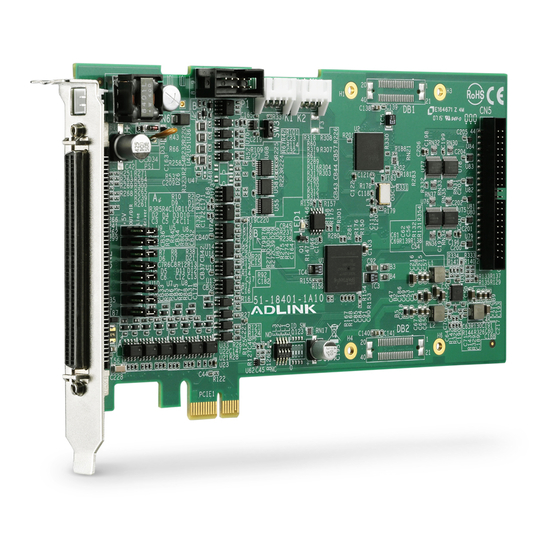
4-Axis Servo/Stepper Motion Control Card
Brand:
ADLINK Technology
| Category:
PCI Card
| Size: 3 MB
Table of Contents
Revision History
2
Table of Contents
5
List of Tables
9
List of Figures
11
1 Introduction
13
Figure 1-1: Pcie-8154 Block Diagram
14
Features
15
Specifications
16
Supported Software
17
Programming Library
18
Motioncreatorpro
18
Available Terminal Board
18
CN2 Pin Assignments: Main Connector
19
Figure 1-2: PCB Layout
19
PCB Layout
19
K1/K2 Pin Assignments: Simultaneous Start/Stop
22
P1 Manual Pulse Generator
22
CN5 Pin Assignments: TTL I/O
23
Table 1-1: P1 Manual Pulse Generator
23
Figure 1-3: IDE 44-Pin Connector Assignment
24
Figure 1-4: DSUB 37-Pin Connector Assignment
24
2 Getting Started
25
Package Contents
25
Pcie-8154 Hardware Installation
25
Hardware Configuration
25
Pcie Slot Selection
25
Installation Procedures
26
Troubleshooting
26
Software Driver Installation
26
JP2 to JP8 Jumper Setting for Pulse Output
27
SW1 Card Index Selection
27
Figure 2-1: Jumper Settings
27
Signal Connections
28
Pulse Output Signals out and dir on CN2
28
Table 2-1: SW1 Card Index
28
Figure 2-2: out and dir Axis Signals
29
Table 2-2: Pulse Output Signals on CN3
29
Table 2-3: out or dir Output by Jumper
29
Encoder Feedback Signals EA, EB and EZ
30
Figure 2-3: OUT/DIR through J2/J3 Connection
30
Figure 2-4: EA, EB, and EZ Input Circuits
31
Table 2-4: EA, EB, and EZ Pin Assignments
31
Figure 2-5: Line Driver Connection Output Circuit
32
Table 2-5: Device/Encoder/Power Connection
32
Figure 2-6: Device/Encoder Connection Circuit
33
Origin Signal ORG
33
Table 2-6: ORG0-ORG3 Pin Assignments
33
End-Limit Signals PEL and MEL
34
Figure 2-7: ORG Input Circuit
34
Table 2-7: End-Limit Signal Pin Assignment
34
Figure 2-8: End-Limit Signals Circuit
35
In-Position Signal INP
35
Table 2-8: INP Signal Connection
35
Alarm Signal ALM
36
Figure 2-9: INP Signal Circuit
36
Table 2-9: Alarm Signal Connection
36
Deviation Counter Clear Signal ERC
37
Figure 2-10: Input Alarm Circuit
37
Table 2-10: ERC Connection
37
Figure 2-11: ERC Circuit
38
General-Purpose Signal SVON
38
Table 2-11: SVON Connection
38
Figure 2-12: SVON Circuit
39
General-Purpose Signal RDY
39
Table 2-12: RDY Signal Connection
39
Figure 2-13: RDY Circuit
40
Multi-Functional Output Pin: DO/CMP
40
Table 2-13: DO/CMP Connection
40
Figure 2-14: DO/CMP Circuit
41
Multi-Functional Input Pin: DI/LTC/SD/PCS/CLR/EMG
41
Table 2-14: DI/LTC/SD/PCS/CLR/EMG Connection
41
Figure 2-15: DI/LTC/SD/PCS/CLR/EMG Circuit
42
Manual Pulse Generator Input Signals PA and PB
42
Table 2-15: Manual Pulse Generator Input Signal Connection
42
Figure 2-16: Manual Pulse Generator Input Signal Circuit
43
Simultaneous Start/Stop Signals STA and STP
43
Figure 2-17: STA & STP Connection
44
Figure 2-18: STA & STP Connection with External Start/Stop
44
Figure 2-19: EDI and EDO Circuit
45
General Purpose TTL I/O EDI and EDO
45
A Appendix: Motioncreatorpro
47
About Motioncreatorpro
47
Initiating Motioncreatorpro
47
A.1 about Motioncreatorpro
47
Motioncreatorpro Introduction
48
Main Menu
48
A.3 Motioncreatorpro Introduction
48
Select Menu
49
Card Information Menu
50
Configuration Menu
51
Single Axis Operation Menu
55
Two-Axis and Four-Axis Operation Menu
63
2D_Motion Menu
68
Help Menu
73
B Appendix: Function Library Reference
75
Data Types
75
Function Naming
75
B.1 Data Types
75
List of Functions
76
B.2 List of Functions
76
Pcie
77
System and Initialization
80
Pulse Input/Output Configuration
84
Velocity Mode Motion
86
Single Axis Position Mode
89
Linear Interpolated Motion
93
Circular Interpolation Motion
101
Helical Interpolation Motion
107
Home Return Mode
111
Manual Pulse Generator Motion
114
Motion Status
117
Motion Interface I/O
118
Interrupt Control
126
Position Control and Counters
129
Position Compare and Latch
135
Continuous Motion
139
Multiple Axes Simultaneous Operation
141
General-Purpose DIO
144
Soft Limit
146
Backlash Compensation / Vibration Suppression
148
Speed Profile Calculation
150
Extended General Purpose TTL Input/Output
153
Return Code
155
C Appendix: Connection Example
157
General Description of Wiring
157
Terminal Board User Guide
157
Important Safety Instructions
159
Getting Service
161
Advertisement
Advertisement
Related Products
ADLINK Technology PCIe-8560
ADLINK Technology PCIe-9842
ADLINK Technology PCIe-FIW Series
ADLINK Technology PCIe-2602
ADLINK Technology PCIe-GIE62
ADLINK Technology PCIe-7432
ADLINK Technology PCIe-FIW64
ADLINK Technology PCIe-U304
ADLINK Technology PCIe-U308
ADLINK Technology PCIe-7442
ADLINK Technology Categories
Computer Hardware
Motherboard
PCI Card
Control Unit
Desktop
More ADLINK Technology Manuals
Login
Sign In
OR
Sign in with Facebook
Sign in with Google
Upload manual
Upload from disk
Upload from URL