Sign In
Upload
Manuals
Brands
ADLINK Technology Manuals
Machine Vision Systems
NEON-202B-JNX
User Manuals: ADLINK Technology NEON-202B-JNX Camera
Manuals and User Guides for ADLINK Technology NEON-202B-JNX Camera. We have
2
ADLINK Technology NEON-202B-JNX Camera manuals available for free PDF download: User Manual
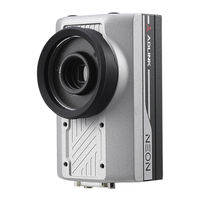
ADLINK Technology NEON-202B-JNX User Manual (57 pages)
AI Smart Camera
Brand:
ADLINK Technology
| Category:
Digital Camera
| Size: 2 MB
Table of Contents
Preface
3
Table of Contents
5
List of Figures
7
List of Tables
9
Introduction
11
Overview
11
Table 1-1: NEON-2000-JNX Model and Sensor Specifications
12
Features
13
General Specifications
14
Table 1-2: NEON-2000-JNX General Specifications
15
Mechanical Dimensions
18
Camera Dimensions
18
USB Type-C Screw Lock Location and Dimensions
18
LED Light Mounting Thread
19
Accessories
20
Connectors and I/O
21
Figure 2-1: NEON-2000-JNX Orientation
21
Bottom Side I/O and Connector Description
22
Figure 2-2: Bottom Side I/O and Connectors
22
Table 2-1: Bottom Side I/O and Connectors
22
D-Sub I/O Connector
23
Figure 2-3: D-Sub I/O Connector
23
Table 2-2: D-Sub I/O Connector Pin Definitions
23
DC Jack
24
Figure 2-4: DC Jack Connector
24
Table 2-3: D-Sub I/O Connector Specification
24
Table 2-4: DC Jack Pin Definitions
24
Top Side I/O and Connector Description
25
Figure 2-5: Top Side I/O and Connectors
25
Table 2-5: Top Side I/O and Connectors
25
Wafer Connector
26
Figure 2-6: Wafer Connector
26
Table 2-6: Wafer Connector Pin Definitions
26
Front Side I/O and Connector Description
27
Figure 2-7: Front Side I/O and Connectors
27
Table 2-7: Front Side I/O and Connectors
27
Getting Started
29
Mounting
29
Figure 3-1: NEON-2000-JNX Mounting Holes
29
Digital I/O Connection Example
30
Figure 3-2: Digital Input Schematic Diagram
30
Figure 3-3: Digital Output Schematic Diagram
30
Attaching a Lens
31
Figure 3-4: Lens Attachment Assembly
31
Power and Peripheral Connections
32
Figure 3-5: Separate Power and Peripheral Connections
32
Figure 3-6: Combined Power and Peripheral Connections
33
Log in
34
Image Capture and Inference
35
NEON-20XB-JNX Series Capture and Adjustment
36
Capture an Image Via Pylon
36
Image Sensor Adjustment Via Pylon
39
Use Apis to Adjust the Image Sensor
48
Neon-20XA Trigger Control
50
Trigger API Function
50
Figure 3-7: Neon-20XA Trigger API Function Options
50
Trigger API Example
51
Important Safety Instructions
53
Consignes de Sécurité Importante
55
Getting Service
57
Advertisement
ADLINK Technology NEON-202B-JNX User Manual (55 pages)
AI Smart Camera
Brand:
ADLINK Technology
| Category:
Machine Vision Systems
| Size: 2 MB
Table of Contents
Preface
3
Table of Contents
5
List of Figures
7
List of Tables
9
1 Introduction
11
Overview
11
Table 1-1: NEON-2000-JNX Model and Sensor Specifications
11
Features
12
General Specifications
13
Mechanical Dimensions
15
Camera Dimensions
15
USB Type-C Screw Lock Location and Dimensions
15
LED Light Mounting Thread
16
Accessories
17
2 Connectors and I/O
19
Figure 2-1: NEON-2000-JNX Orientation
19
Bottom Side I/O and Connector Description
20
Figure 2-2: Bottom Side I/O and Connectors
20
Table 2-1: Bottom Side I/O and Connectors
20
D-Sub I/O Connector
21
Figure 2-3: D-Sub I/O Connector
21
Table 2-2: D-Sub I/O Connector Pin Definitions
21
DC Jack
22
Figure 2-4: DC Jack Connector
22
Table 2-3: D-Sub I/O Connector Specification
22
Table 2-4: DC Jack Pin Definitions
22
Top Side I/O and Connector Description
23
Figure 2-5: Top Side I/O and Connectors
23
Table 2-5: Top Side I/O and Connectors
23
Figure 2-6: Wafer Connector
24
Table 2-6: Wafer Connector Pin Definitions
24
Wafer Connector
24
Front Side I/O and Connector Description
25
Figure 2-7: Front Side I/O and Connectors
25
Table 2-7: Front Side I/O and Connectors
25
3 Getting Started
27
Mounting
27
Figure 3-1: NEON-2000-JNX Mounting Holes
27
Digital I/O Connection Example
28
Figure 3-2: Digital Input Schematic Diagram
28
Figure 3-3: Digital Output Schematic Diagram
28
Attaching a Lens
29
Figure 3-4: Lens Attachment Assembly
29
Power and Peripheral Connections
30
Figure 3-5: Separate Power and Peripheral Connections
30
Figure 3-6: Combined Power and Peripheral Connections
31
Image Capture and Inference
32
Inference Concepts and Sample
34
Sample Inference Steps
35
Use Pylon to Capture and Adjust the Sensor
36
Capture an Image Via Pylon
36
Image Sensor Adjustment Via Pylon
39
Use Apis to Adjust the Image Sensor
48
Important Safety Instructions
51
Consignes de Sécurité Importante
53
Getting Service
55
Advertisement
Related Products
ADLINK Technology NEON-2000-JT2-X Series
ADLINK Technology NEON-201B-JT2-X
ADLINK Technology NEON-202B-JT2-X
ADLINK Technology NEON-203B-JT2-X
ADLINK Technology NEON-204B-JT2-X
ADLINK Technology NEON-2000-JNX Series
ADLINK Technology NEON-201B-JNX
ADLINK Technology NEON-203B-JNX
ADLINK Technology NEON-204B-JNX
ADLINK Technology NEON-202A-JNX
ADLINK Technology Categories
Computer Hardware
Motherboard
PCI Card
Control Unit
Desktop
More ADLINK Technology Manuals
Login
Sign In
OR
Sign in with Facebook
Sign in with Google
Upload manual
Upload from disk
Upload from URL