Sign In
Upload
Manuals
Brands
ADLINK Technology Manuals
Control Unit
MPC-8164
ADLINK Technology MPC-8164 Manuals
Manuals and User Guides for ADLINK Technology MPC-8164. We have
1
ADLINK Technology MPC-8164 manual available for free PDF download: User Manual
ADLINK Technology MPC-8164 User Manual (311 pages)
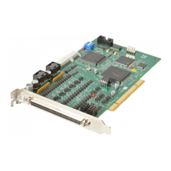
Advanced 4-Axis Servo/Stepper Motion Control Card
Brand:
ADLINK Technology
| Category:
Control Unit
| Size: 2 MB
Table of Contents
Table of Contents
5
List of Tables
10
1 Introduction
13
Figure 1-1: PCI-8164 Block Diagram
14
Figure 1-2: MPC-8164 Block Diagram
15
Figure 1-3: PXI-8164 Block Diagram
16
Figure 1-4: Application Building Flow Chart
17
Features
18
Pci-8164
18
Mpc-8164
20
Pxi-8164
21
Specifications
23
General Specifications
24
Software Support
26
Programming Library
26
Motion Creator
26
2 Installation
27
Package Contents
28
PCI-8164 Layout
29
Figure 2-1: PCI-8164 PCB Layout
29
Figure 2-2: PCI-8164 Face Plate
29
MPC-8164 Layout
30
Figure 2-3: MPC-8164 PCB Layout
30
Figure 2-4: MPC-8164 Face Plate
30
PXI-8164 Layout
31
Figure 2-5: PXI-8164 Layout and Front Panel
31
PCI-8164/PXI-8164 Hardware Installation
32
Hardware Configuration
32
PCI Slot Selection
32
Installing the PCI-8164 Card
32
Installing the PXI-8164 Card
33
MPC-8164 Hardware Installation
34
Hardware Configuration
34
Driver Installation
36
CN1 Pin Assignments: External Power Input
37
(PCI-8164 Only)
37
CN3 Pin Assignments: Manual Pulse Input
38
(PCI-8164 Only)
38
J4 Pin Assignments: Manual Pulse Input
39
(PXI-8164 Only)
39
CN3 Pin Assignments: General Purpose DIO
40
(MPC-8164 Only)
40
J3 Pin Assignments: Isolated DIO
41
(PXI-8164 Only)
41
CN2 Pin Assignments: Main Connector
42
CN4 Pin Assignments: Simultaneous Start/Stop
44
(PCI-8164 Only)
44
CN5 Pin Assignment: TTL Output (PCI-8164 Only)
45
Jumper Setting for Pulse Output (PCI-8164 Only)
46
Switch Setting for el Logic
47
CN3 Pin Assignment: General Purpose DI/DO Ports
48
(MPC-8164 Only)
48
S2 Card ID Switch Setting (PXI-8164 Only)
49
3 Signal Connections
51
Pulse Output Signals out and dir
52
Encoder Feedback Signals EA, EB and EZ
55
Origin Signal ORG
58
End-Limit Signals PEL and MEL
59
Ramping-Down and PCS
60
In-Position Signal INP
61
Alarm Signal ALM
62
Deviation Counter Clear Signal ERC
63
General-Purpose Signal SVON
64
General-Purpose Signal RDY
65
Position Compare Output Pin: CMP
66
Position Latch Input Pin: LTC
67
Pulser Input Signals PA and PB (PCI-8164 Only)
68
Simultaneously Start/Stop Signals STA and STP
69
(PCI-8164 Only)
69
General Purpose TTL Output (PCI-8164 Only)
71
Termination Board
72
General Purpose DIO (MPC-8164/PXI-8164 Only)
73
Isolated Input Channels
74
Isolated Output Channels
74
Example of Input Connection
75
Example of Output Connections
76
4 Operation Theory
77
Motion Control Modes
78
Pulse Command Output
79
Velocity Mode Motion
83
Trapezoidal Motion
84
S-Curve Profile Motion
87
Linear Interpolation for 2-4 Axes
89
Circular Interpolation for 2 Axes
94
Circular Interpolation with Acc/Dec Time
96
Relationship between Velocity and Acceleration Time
97
Continuous Motion
100
Home Return Mode
107
Home Search Mode
115
Manual Pulser Mode (PCI-8164 Only)
116
Synchronous Starting Modes
117
The Motor Driver Interface
119
Inp
119
Alm
121
Erc
122
SVON and RDY
123
The Limit Switch Interface and I/O Status
124
Sd/Pcs
124
Org
127
Counters
128
Command Position Counter
128
Feedback Position Counter
129
Position Error Counter
131
General Purpose Counter
132
Target Position Recorder
134
Multiple PCI-8164 Card Operation (PCI-8164 Only)
135
Change Position or Speed on the Fly
136
Change Speed on the Fly
136
Change Position on the Fly
141
Position Compare and Latch
144
Comparators of the 8164
144
Position Compare with Trigger Output
146
Position Latch
150
Hardware Backlash Compensator and Vibration Suppression
151
Software Limit Function
152
Interrupt Control
153
PXI Trigger Bus (PXI-8164 Only)
159
5 Motion Creator
161
Execute Motion Creator
162
Notes on Motion Creator
163
Using Motion Creator
164
Main Menu
164
Interface I/O Configuration Menu
164
Pulse I/O and Interrupt Configuration Menu
167
Operation Menu
168
6 Function Library
175
List of Functions
175
C/C++ Programming Library
186
Initialization
187
Pulse Input/Output Configuration
191
Velocity Mode Motion
194
Single Axis Position Mode
198
Linear Interpolated Motion
205
Circular Interpolation Motion
213
Home Return Mode
223
Manual Pulser Motion
226
Motion Status
230
Motion Interface I/O
232
Motion I/O Monitoring
236
Interrupt Control
238
Position Control and Counters
246
Return Code
250
Position Compare and Latch
251
Continuous Motion
261
Multiple Axes Simultaneous Operation
263
General-Purposed TTL Output (PCI-8164 Only)
269
General-Purposed DIO (MPC-8164/PXI-8164 Only)
271
Card ID (PXI-8164 Only)
273
PXI Trigger Bus (PXI-8164 Only)
274
7 Connection Example
277
General Wiring Description
277
Figure 7-1: System Integration with PCI-8164
278
Connection Example with Servo Driver
279
Figure 7-2: Connection of PCI-8164 with Panasonic Driver
280
Figure 7-3: Connection of PCI-8164 with SANYO Driver
281
Wiring with DIN-814M
282
PIN Assignments
283
Signal Connections
286
Mechanical Dimensions
287
Wiring with DIN-814P
288
Mechanical Dimensions
289
PIN Assignment
290
How to Wire
292
Wiring with DIN-814PA
293
Wiring Example
295
Mechanical Dimensions
297
PIN Assignment
298
Wiring with DIN-814M-J3A
300
PIN Assignment
301
Wiring with DIN-814Y
304
PIN Assignment
305
8 Appendix
307
Color Code of CN3 Cable (MPC-8164 Only)
307
Warranty Policy
309
Advertisement
Advertisement
Related Products
ADLINK Technology MXC-6201D
ADLINK Technology MXC-6403D
ADLINK Technology Matrix MXE-5104M
ADLINK MVP-6021
ADLINK Technology MVP-6020 Series
ADLINK Technology MVP-6011
ADLINK Technology MVP-6013
ADLINK Technology MXE-5302
ADLINK Technology MXE-5603
ADLINK Technology MCS-2040
ADLINK Technology Categories
Computer Hardware
Motherboard
PCI Card
Control Unit
Desktop
More ADLINK Technology Manuals
Login
Sign In
OR
Sign in with Facebook
Sign in with Google
Upload manual
Upload from disk
Upload from URL