Sign In
Upload
Manuals
Brands
ADLINK Technology Manuals
Single board computers
cPCI-6910VS/M2G
ADLINK Technology cPCI-6910VS/M2G Manuals
Manuals and User Guides for ADLINK Technology cPCI-6910VS/M2G. We have
1
ADLINK Technology cPCI-6910VS/M2G manual available for free PDF download: User Manual
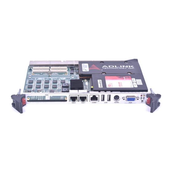
ADLINK Technology cPCI-6910VS/M2G User Manual (142 pages)
6U CompactPCI Single Board Computer with Dual-Core Intel Xeon Processor LV/ULV
Brand:
ADLINK Technology
| Category:
Single board computers
| Size: 6 MB
Table of Contents
Preface
6
Using this Manual
7
Conventions
9
Getting Service
10
Related Documentation
12
Table of Contents
14
List of Figures
20
List of Tables
22
Introduction
24
Features
26
Block Diagrams
27
Cpci-6910 with Cpci-R6910 Block Diagram
27
Figure 1-1: Cpci-6910 with Cpci-R6910 Block Diagram
27
Cpci-R6911 Block Diagram
28
Figure 1-2: Cpci-R6911 Block Diagram
28
Product List
29
Cpci-6910 Configurations
29
Rear Transition Modules
30
Package Contents
31
CPU Module
31
Rear Transition Module (RTM)
31
Optional Components
31
Specifications
34
Cpci-6910 SBC Specifications
34
Cpci-R6910/Cpci-R6911 RTM Specifications
37
I/O Connectivity Table
38
Power Consumption
39
Idle Mode under DOS
39
Idle Mode under Linux
40
Full-Load CPU Mode under Windows® XP
40
Idle Mode under Windows® XP
40
Functional Description
42
Processor
42
Chipset
42
Memory
42
PCI Express (High-Speed Serial I/O)
44
Hub Interface 1.5
44
Intel 6300ESB I/O Controller Hub (ICH)
45
Ultra ATA100/66/33 IDE
46
Usb 2.0
46
Lpc/Firmware Hub
46
System Management Bus
46
Uart
47
Watchdog Timer
47
Real Time Clock
47
PCI 32-Bit and PCI-X Interface
47
ATI ES1000 VGA Chip
48
Hardware Monitor
48
PCI Resource Allocation
48
PCI-X to PCI-X Bridge
49
Jumpers and Connectors
50
Cpci-6910 Board Layout
51
Cpci-6910 Front Panel
52
System LED Indication
52
Cpci-6910 Daughterboard Layout
53
Db-6910Ide
53
Db-6910Sat
53
Rear Transition Modules
54
Cpci-R6910 Board and Daughterboard Layouts
54
Db-R6910Sas
55
Db-R6910Sat
55
Cpci-R6911 Board Layout
56
Connector Pin Assignments
57
USB Connectors
57
Ethernet (RJ-45) Connector
57
VGA Connector
58
PS2 Connector
58
Serial Port (COM1)
59
Compactflash® Connector
60
Hard Disk Drive Board to Board Connector
61
On CPU Blade - SATA/IDE Connector
61
On Rear I/O - SATA/SAS Connector
62
Compactpci® J1 Pin Assignment
63
Compactpci® J2 Pin Assignment
64
Compactpci® J3 Pin Assignment
65
Compactpci® J4 Pin Assignment
66
Compactpci® J5 Pin Assignment
67
Switches
68
Clear CMOS Switch (SWZ1)
68
COM and IPMI Switch (SWZ2)
68
PCB Switch (SW1)
69
Miniature Switch on the Lower Ejector (Front Panel)
70
Cpci-R6911 RTM Switches (SWY1, 2, 3 & 4)
71
Getting Started
74
Tools
74
Installing the CPU
75
Installing the Heatsink
77
Installing the Hard Disk Drive
78
On the Cpci-6910
78
On the Cpci-R6910 Rear Transition Module
81
Installing the Compactflash® Card Slot
84
Installing the Cpci-6910 to the Chassis
86
Installing the Cpci-R6910 to the Chassis
86
Driver Installation
88
Installing the VGA Driver
89
Windows® 2000
89
Windows® XP Professional
90
Watchdog Timer
92
WDT Overview
92
Figure 7-1: WDT Block Diagram
92
Configuration Registers
93
GPIO Control Registers
95
WDT Programming Procedure
96
Utilities
97
Intel® Preboot Execution Environment (PXE)
97
BIOS Setup
98
Navigating through the BIOS Menus
99
Figure 8-1: Control Keys & Information Bar in Main Menu
99
Figure 8-2: Control Keys in Sub-Menu
99
Standard CMOS Features
100
Advanced BIOS Features
104
Advanced Chipset Features
108
Integrated Peripherals
110
Pnp/Pci Configuration
115
Frequency/Voltage Control
116
Load Fail-Safe Defaults
117
Setting the Supervisor and User Passwords
118
Saving and Exiting the BIOS Setup
119
IPMI Interface
120
Audience
120
BMR-AVR-Cpci Command Summary
120
OEM Commands Summary Table
122
Oemshowrevision
122
Oemrescangainput
123
Oemtestfunction
123
Oemreportgeoaddress
123
Oemenablesmbus
123
Oemdisablesmbus
124
Oemdispdebugvariable
124
Oemresethost
124
Oempoweroff
125
Oempoweron
125
Compactpci® Address Map
126
IPMI Sensors List
127
Cpci-6910 B2 and Earlier Versions
127
Cpci-6910 B3 and Future Versions
127
Firmware Revision History
127
Known Issues
129
Appendix: Using Serial Console
130
Introduction
130
Before Using Serial Console
130
Setting up the Server Computer
131
Using Serial Console with Hyperterminal
131
Figure 10-1: Null Modem Connection
131
Performing Operations in the Hyperterminal Console
136
Important Safety Instructions
138
Warranty Policy
140
Advertisement
Advertisement
Related Products
ADLINK Technology cPCI-6910VS/M2G-GP
ADLINK Technology cPCI-6910VS/DCX20/M2G
ADLINK Technology cPCI-6841 Series
ADLINK Technology cPCI-6840 Series
ADLINK Technology cPCI-6840V
ADLINK Technology cPCI-6880 Series
ADLINK Technology cPCI-6842 Series
ADLINK Technology cPCI-6842-2
ADLINK Technology cPCI-R6000D Series
ADLINK Technology cPCI-R6101
ADLINK Technology Categories
Computer Hardware
Motherboard
PCI Card
Control Unit
Desktop
More ADLINK Technology Manuals
Login
Sign In
OR
Sign in with Facebook
Sign in with Google
Upload manual
Upload from disk
Upload from URL