Sign In
Upload
Manuals
Brands
ADCMT Manuals
Multimeter
7351E
ADCMT 7351E Manuals
Manuals and User Guides for ADCMT 7351E. We have
1
ADCMT 7351E manual available for free PDF download: Operation Manual
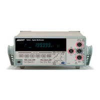
ADCMT 7351E Operation Manual (186 pages)
Brand:
ADCMT
| Category:
Multimeter
| Size: 1 MB
Table of Contents
Table of Contents
3
1 Introduction
11
Contents of this Manual
11
Product Overview
12
2 Precautions
13
If a Fault Occurs
13
Removing the Case
13
Power Fuse
13
Electromagnetic Interference
14
Note When Turning on the Power
14
3 Setup
15
Inspection on Delivery
15
Standard Accessories
16
Installation Environment
17
Protecting against Electrostatic Discharge
18
Electrostatic Countermeasures for the Work Floor and Human Body
18
Electrostatic Countermeasures for the Workbench
18
ESD Countermeasures
18
Accessories
19
Input Cable
19
Caution When Connecting Peripherals
21
Power Requirements
22
Checking the Power Supply Voltage
22
Indication of the Set Power Supply Voltage
22
Relation Table between AC Power Supply Voltage and Indication of Set Power Supply Voltage
22
Changing the Power Supply Voltage
23
Connecting the Power Cable
25
Selecting the Power Supply Frequency
25
4 Quick Start
27
Panel Description
27
Front Panel Description
27
Display Section
28
Power Switch
28
Measurement Function Keys
28
Display Section Description
28
Measurement Range Selection Keys
29
Sampling Selection Keys
29
Calculation Selection Keys
29
MENU/ENTER Key
29
SHIFT/EXIT/LOCAL Key
30
Front Input Section for Measurement
30
CAT II (Marking)
30
Rear Panel Description
31
Rear Panel Description (7351A)
31
Rear Panel Description (7351E + Option 03)
32
Basic Operation
33
Measurement Functions
33
DC Voltage Measurement (DCV)
33
Maximum Allowable Applied Voltage (DCV)
33
AC Voltage Measurement (ACV and ACV(AC+DC))
34
Measurement Range and Input Impedance (DCV)
34
Maximum Allowable Applied Voltage (ACV and ACV (AC+DC))
34
Resistance Measurement (2W and LP-2W)
35
AC Voltage Measurement (ACV and ACV (AC+DC))
35
Maximum Allowable Applied Voltage (2W and LP-2W)
35
DC Current Measurement (DCI)
36
Maximum Allowable Applied Current and Protection Function (DCI)
36
AC Current Measurement (ACI and ACI (AC+DC))
38
Maximum Allowable Applied Current and Protection Function (ACI and ACI (AC+DC))
38
Continuity Measurement
39
AC Current Measurement (ACI and ACI (AC+DC))
39
Diode Measurement
40
Maximum Allowable Applied Voltage (Continuity)
40
Maximum Allowable Applied Voltage (Diode)
40
Frequency Measurement (FREQ)
41
Maximum Allowable Applied Voltage (FREQ)
42
Setting the Measurement Range
43
Changing the Measurement Speed and Display Digit
43
Measurement Speed (A) When in the HOLD off (Trigger Source: IMMED)
43
Measurement Speed (B) When in the HOLD on (Trigger Source: EXT)
44
Measurement Speed (B) When in the HOLD on (Trigger Source: BUS)
44
Measurement Speed (B) When in the HOLD on (Trigger Source: BUS
45
Sampling Rate and Display Digits
45
5 Menu Operation and Function Description
47
Menu
47
How to Navigate the Menus
47
Menu Operation
47
Menu Operation Key and Function
49
Menu List
50
Measurement Functions
54
Continuity Measurement
54
Measurement Range and Auto-Range
54
Measurement Function and Range Structure
54
Auto-Range
55
Auto-Zero Operation
56
Display Mode Setting
57
Display Digit Setting
57
Measurement Sequence
58
Trigger Function
59
Trigger Model
59
Trigger System Operation
60
Trigger Source Selection
61
Trigger Delay (Td)
61
Trigger Delay Time, Setting Resolution, and Accuracy
61
Calculation Functions
63
Calculation System Diagram
63
NULL Calculation
64
Smoothing Calculation
65
Scaling Calculation
68
Db and Dbm Calculation
70
Comparator Calculation
72
MAX/MIN Calculation
75
5.9.7 Statistical Calculation
77
5.10 Saving and Loading the Measurement Condition Settings
79
Auto-Loading When Turning on the Power
79
Saving the Setting Parameters
79
Loading the Setting Parameters
79
5.11 Storing and Recalling the Measurement Data
80
Memory Store
80
Memory Recall
80
Memory Clear
80
5.12 System Settings
81
Power Supply Frequency
81
Disabling Functions
81
Relationship According to Disabling the Function
82
Front Panel Disabling Function
83
Error Queue
85
6 How to Use the Interface
87
Interface Selection
87
Response to the *IDN? Command
87
Gpib (7351A)
89
Overview
89
Interface Functions
89
6.2.2 Precautions in Use of GPIB
90
Standard Bus Cable
90
GPIB Setting
91
EIA-232] (7351E + Option 03)
92
Overview
92
Setting
93
Output Data Format
94
Sample Program (RS-232)
95
Usb
97
Overview
97
USB Specifications
97
Setting up the USB Port
97
Connecting to a Personal Computer
97
Usbid Setting
97
Control Signal (7351A, 7351E + Option 03)
98
External Trigger Terminal (TRIGGER IN)
98
Simple Equivalent Circuit of Trigger Input Terminal
98
Measurement Complete Signal Terminal (COMPLETE OUT)
99
Simple Equivalent Circuit of Complete Signal Output Terminal
99
Comparator Output (7351E + Option 03)
100
Signal Output Pin
100
Optical Semiconductor Relay Contact and TTL Logical Output (A)
101
Optical Semiconductor Relay Contact and TTL Logical Output (B)
101
Command Reference
102
Selecting the Command Language
102
Compatibility
103
Output Data Format
104
ADC Command Reference
108
SCPI Command Reference
117
Status Register Structure
127
6.7.5 Status Register Structure
128
Status Byte Register Structure
130
Status Byte Register (STB)
131
Standard Event Status Register (SESR)
133
Measurement Event Register (MER)
134
Questionable Event Register (QER)
135
Operation Event Register (OER)
136
Sample Programs (Command Used in ADC CORPORATION)
137
Sample Programs (SCPI Command)
139
7 Specifications
141
DC Voltage Measurement (DCV)
141
AC Voltage Measurement (ACV, ACV(AC+DC))
142
Resistance Measurement (2W, LP-2W)
144
DC Current Measurement (DCI)
145
AC Current Measurement (ACI, ACI(AC+DC))
146
Frequency Measurement (FREQ)
148
Continuity Measurement
149
Diode Measurement
149
Measurement Time and Display Digits
150
7.1.10 Calculation Functions
152
Interface Specifications
153
General Specifications
155
8 Maintenance
157
Replacing Fuses
157
Replacing a Power Fuse
157
Replacing a Protection Fuse
157
How to Check Protection Fuses
158
How to Replace Protection Fuses
159
Input Terminal Protection Fuse
159
Cleaning
160
Cleaning the Outside
160
Cleaning Others
160
Calibration
161
Preparing for Calibration
161
Calibration Standards
161
Calibration Point
162
Calibration Point
163
Calibration Procedure
164
Replacing Parts with Limited Life
167
Parts with Limited Life
167
Product Disposal and Recycle
168
Storage
170
Transportation
170
Notes Regarding Repair, Replacement, and Periodic Calibration
171
Before Asking for Repair
171
Contacting ADC CORPORATION for Repair or Calibration
172
Address and Phone Number
172
System Recovery Procedure
173
Initial Values of Setting Parameters
174
8.10 Self-Test
176
Display and Key Tests
176
Self-Test Items
176
8.11 Error Message List
178
Dimensional Outline Drawing
181
Alphabetical Index
185
Advertisement
Advertisement
Related Products
ADCMT 7451A
ADCMT 7461A
ADCMT 7461P
ADCMT 7351A
ADCMT 7352A
ADCMT 7352E
ADCMT 7481
ADCMT 7482
ADCMT Categories
Measuring Instruments
Multimeter
Portable Generator
Monitor
Accessories
More ADCMT Manuals
Login
Sign In
OR
Sign in with Facebook
Sign in with Google
Upload manual
Upload from disk
Upload from URL