Sign In
Upload
Manuals
Brands
ABB Manuals
Industrial Equipment
ACS800-17-0770-3
ABB ACS800-17-0770-3 Manuals
Manuals and User Guides for ABB ACS800-17-0770-3. We have
1
ABB ACS800-17-0770-3 manual available for free PDF download: Hardware Manual
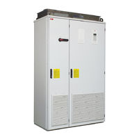
ABB ACS800-17-0770-3 Hardware Manual (236 pages)
ACS800 55 to 2500 kW / 75 to 2800 hp
Brand:
ABB
| Category:
Controller
| Size: 9 MB
Table of Contents
Table of Contents
13
Safety Instructions
5
What this Chapter Contains
5
Usage of Warnings and Notes
5
Installation and Maintenance Work
6
Grounding
9
Fibre Optic Cables
10
Operation
11
Permanent Magnet Motor Drives
12
Installation and Maintenance Work
12
Inverter Control Program
12
Operation
12
Table of Contents
13
Table of Contents
20
About this Manual
21
What this Chapter Contains
21
Target Audience
21
Common Chapters for Multiple Products
21
Categorization According to the Frame Size
21
Contents
22
Installation and Commissioning Flowchart
23
Inquiries
24
Terms and Abbreviations
24
The ACS800-17
27
What this Chapter Contains
27
Cabinet Line-Up
27
Frame R6
28
Frame R7I
29
Frame R8I
30
Swing-Out Frame
31
Cabling Direction
33
Single-Line Circuit Diagram of the Drive
35
Operation Principle
36
AC Voltage and Current Waveforms
36
Line-Side Converter
36
Frame R6
37
Frame R7 and up
37
Motor-Side Converter
37
Controls
38
Control Interfaces of the Drive
38
Air Circuit Breaker (Q1 in Frame Size 2×R8I and Up)
39
Auxiliary Power Switch (Q100 in Frame Size 2×R8I and Up)
39
Door Switches
39
Earthing Switch (Q9 in Frame Size 2×R8I and Up)
39
Main Switch-Disconnector (Q1 in Frame Size R6 to R8I)
39
Other Door Switches
39
Control Panel
40
To Control the Inverter Unit
40
To Control the Supply Unit
40
Block Diagram: Reference Select
41
Fieldbus Control of the Line-Side Converter
41
Type Code
42
Frame Sizes R6, R7I and R8I
42
Frame Sizes 2×R8I to 6×R8I
43
Mechanical Installation
47
What this Chapter Contains
47
General
47
Required Tools
47
Moving the Unit
48
By Crane
48
By Fork-Lift or Pallet Truck
49
Laying the Unit on Its Back
49
On Rollers
49
Final Placement of the Unit
50
Before Installation
51
Delivery Check
51
Installation Procedure
52
Fastening the Cabinet to the Floor (Non-Marine Units)
53
Clamping
53
Holes Inside the Cabinet
54
Fastening the Unit to the Floor and Wall (Marine Units)
55
Joining the Shipping Splits
56
Procedure
56
Connecting the DC Busbars and the PE Busbar
57
DC Busbars
58
PE Busbar
58
Miscellaneous
59
Cable Conduit in the Floor below the Cabinet
59
Cooling Air Intake through Bottom of Cabinet
60
Example
60
Electric Welding
61
Planning the Electrical Installation
63
What this Chapter Contains
63
Motor Selection and Compatibility
63
Protecting the Motor Insulation and Bearings
64
Requirements Table
64
Permanent Magnet Synchronous Motor
68
Thermal Overload and Short-Circuit Protection
68
Supply (AC Line) Cable Short-Circuit Protection
68
Earth Fault (Ground Fault) Protection
69
Emergency Stop Devices
69
Prevention of Unexpected Start-Up
70
Safe Torque off
71
ATEX-Certified Thermal Motor Protection
71
Selecting the Power Cables
72
General Rules
72
Alternative Power Cable Types
73
Additional US Requirements
74
Armored Cable / Shielded Power Cable
74
Conduit
74
Motor Cable Shield
74
Power Factor Compensation Capacitors
75
Equipment Connected to the Motor Cable
75
Bypass Connection
75
Installation of Safety Switches, Contactors, Connection Boxes, Etc
75
Before Opening an Output Contactor (in DTC Motor Control Mode)
76
Relay Output Contacts and Inductive Loads
76
Selecting the Control Cables
77
Coaxial Cable (for Use with Advant Controllers AC 80/AC 800)
77
Control Panel Cable
77
Relay Cable
77
Connection of a Motor Temperature Sensor to the Drive I/O
78
Installation Sites above 2000 Metres (6562 Feet)
78
Routing the Cables
78
Control Cable Ducts
79
Electrical Installation
81
What this Chapter Contains
81
Option Coding
81
Before Installation
82
Checking the Insulation of the Assembly
82
Drive
82
EMC Filter +E202
82
IT (Ungrounded) Systems
82
Motor and Motor Cable
82
Supply Cable
82
EMC Filter +E200
83
EMC Filter +E210
83
Input Power Connection - Frame R6
84
Connection Diagram
84
Connection Procedure
84
Input Power Connection - Frame R7I
85
Connection Diagram
85
Connection Procedure
85
Input Power Connection - Frame R8I
86
Connection Diagram
86
Connection Procedure
86
Input Power Connection - Frame 2×R8I and up
87
Connection Diagram
87
Connection Procedure
87
Grounding of Shielded Single-Core Input Cables
88
Motor Connection - Frame R6
88
Connection Diagram
88
Connection Procedure
88
Motor Connection - Frame R7I
89
Connection Diagram
89
Connection Procedure
89
Motor Connection - Frame R8I Units Without Option +E202 or +H359
90
Connection Diagram
90
Connection Procedure
90
Motor Connection - Frame R8I with Option +E202 but Without +H359
91
Connection Diagram
91
Connection Procedure
91
Output Busbars
91
Motor Connection - Units with Common Motor Terminal Cubicle (+H359)
93
Connection Diagram
93
Connection Procedure
93
Motor Connection - Frame 2×R8I and up Without Common Motor Terminal Cubicle
94
Connection Diagram
94
Output Busbars
94
Connection Procedure
95
Control Connections
96
Connection Procedure
96
Drive Control Connections
96
Supply Unit Control Connections
96
Installation of Optional Modules and PC
98
Cabling of I/O and Fieldbus Modules
98
Cabling of Pulse Encoder Interface Module
98
Fibre Optic Links
98
Tap Settings of the Auxiliary Voltage Transformer (Frame R8I and Up)
99
Motor Control and I/O Board (RMIO)
101
What this Chapter Contains
101
To Which Products this Chapter Applies
101
Note on Cabinet-Installed ACS800 Drives
101
Note on Terminal Labelling
101
External Control Connections (Non-US)
102
External Control Connections (US)
103
RMIO Board Specifications
104
Analogue Inputs
104
Analogue Outputs
104
Auxiliary Power Output
104
Constant Voltage Output
104
Digital Inputs
104
24 V DC Power Input
105
DDCS Fibre Optic Link
105
Relay Outputs
105
Installation Checklist and Start-Up
107
What this Chapter Contains
107
Installation Checklist
107
Start-Up Procedure
108
Basic Checks with no Voltage Connected
108
Connecting Voltage to Input Terminals and Auxiliary Circuit
108
Checks with the Supply Unit Running
109
Inverter Control Program Set-Up
109
Starting the Supply Unit
109
Supply Unit (Line-Side Converter) Program Set-Up
109
ACS800-17-Specific Parameters in the IGBT Supply Control Program
110
On-Load Checks
110
Terms and Abbreviations
110
Parameters
111
Default Values of Parameters with the ACS800-17
112
ACS800-17-Specific Parameters in the Inverter Control Program
113
Terms and Abbreviations
113
The Inverter Control Program
114
Maintenance
115
What this Chapter Contains
115
Safety Instructions
115
Maintenance Intervals
115
Reduced Run Capability
116
Checking and Replacing the Air Filters
116
Quick Connectors (Frame R8I and Up)
117
Cooling Fans
118
Supply/Inverter Module Cooling Fan Replacement (Frame R6)
118
Supply/Inverter Module Cooling Fan Replacement (Frame R7I)
119
LCL Filter Module Cooling Fan Replacement (Frame R7I)
120
Module Fan Replacement Procedure
121
Supply and Inverter Module Cooling Fan Replacement (Frame R8I and Up)
121
LCL Filter Cooling Fan Replacement (Frame R8I and Up)
122
LCL Filter Fan Replacement Procedure
122
Cabinet Fan Replacement (Frame R6)
123
Cabinet Fan Replacement (Frame R8I with IP21-42)
123
Cabinet Fan Replacement (Frame 2Xr8I and up with IP21-42)
124
Cabinet Fan Replacement (Frame R8I and up with IP54)
125
Heatsinks
126
Capacitors
126
Capacitor Replacement
126
Reforming
126
Power Module Replacement (Frame R8I and Up)
127
Extracting the Module from the Cubicle
128
Inserting the Module into the Cubicle
131
Fault Tracing
133
Faults and Warnings Displayed by the CDP-312R Control Panel
133
Conflicting ID Numbers
133
Warning/Fault Message from Unit Not Being Monitored by Control Panel
133
Leds of the Drive
134
Technical Data
135
What this Chapter Contains
135
IEC Ratings
135
Derating
136
Symbols
136
Altitude Derating
137
Temperature Derating
137
NEMA Ratings
138
Symbols
139
ACS800-17 Frame Sizes and Power Module Types
139
AC Fuses
140
DC Fuses
142
Input Power Connection
143
Motor Connection
145
Efficiency
148
Cooling
148
Degrees of Protection
148
Ambient Conditions
148
Materials
149
Tightening Torques for Power Connections
150
Applicable Standards
150
CE Marking
151
Compliance with the European EMC Directive
151
Compliance with the European Low Voltage Directive
151
Compliance with the European Machinery Directive
151
Declaration of Conformity
152
Compliance with en 61800-3:2004
154
Category C2
154
Category C3
154
Definitions
154
C-Tick" Marking
155
Category C4
155
What this Chapter Contains
157
Cabinet Line-Ups
157
R7I
157
R8I
158
4×R8I
159
Frame R6
160
Frame R7I
162
Frame R7I with +E202/+E205/+H359
167
Frame R7I, Marine Construction (+C121)
175
Frame R8I
178
Frame R8I with +E202/+H359
184
Frame 2×R8I
186
Frame 3×R8I
196
Frame 4×R8I
202
Frame 5×R8I
208
Frame 6×R8I
220
Product and Service Inquiries
235
Product Training
235
Providing Feedback on ABB Drives Manuals
235
Document Library on the Internet
235
Advertisement
Advertisement
Related Products
ABB ACS800-17-0780-5
ABB ACS800-17-0790-7
ABB ACS800-17-0070-3
ABB ACS800-17-0140-3
ABB ACS800-17-0390-3
ABB ACS800-17-0490-3
ABB ACS800-17-0120-5
ABB ACS800-17-0260-5
ABB ACS800-17-0070-7
ABB ACS800-17-0100-7
ABB Categories
Industrial Equipment
Controller
Measuring Instruments
Battery Charger
DC Drives
More ABB Manuals
Login
Sign In
OR
Sign in with Facebook
Sign in with Google
Upload manual
Upload from disk
Upload from URL