Sign In
Upload
Manuals
Brands
abaco systems Manuals
Single board computers
V7768
abaco systems V7768 Manuals
Manuals and User Guides for abaco systems V7768. We have
1
abaco systems V7768 manual available for free PDF download: Hardware Reference Manual
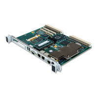
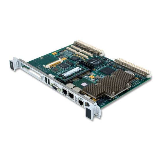
abaco systems V7768 Hardware Reference Manual (92 pages)
Intel Core Duo Processor VME Single Board Computer
Brand:
abaco systems
| Category:
Single board computers
| Size: 3.98 MB
Table of Contents
Figure 1 V7768 Block Diagram
9
Figure 2 Illustration of V7768
10
Figure 3 V7769 Block Diagram
11
Figure 4 Illustration of V7769
12
Table of Contents
16
1 Installation and Setup
21
Unpacking Procedures
21
Hardware Setup
21
V7768 Board Layout Information
22
Figure 1-1 V7768 Connector Locations
22
Table 1-1 V7768 Connectors and Switches
23
Table 1-2 Universe IID Mapping/Sysfail Generation - Switch (S6)
23
Table 1-3 VME Strapping - Switch (S7)
23
Table 1-4 VME System Controller - Switch (S10)
24
Table 1-5 Battery Enable - Switch (S11)
24
Table 1-6 Password Clear/Bios Boot Mode - Switch (S12)
24
Figure 1-2 COM1 Termination Headers (E13, E14, E17)
25
Table 1-7 COM1 Configuration (RS232/RS422 Select) - Header (E13, E14, E17)
25
Mezzanine Board Layout Information (V7769)
26
Figure 1-3 Mezzanine Board Connector Locations
26
Installation
27
Table 1-8 Mezzanine Connectors and Switches
27
Table 1-9 Switch (S2) Settings
27
BIOS Setup
28
Figure 1-4 Installing the PMC Card on the V7768/V7769
29
Figure 1-5 Backside Mounting for the PMC Card
30
Figure 1-6 Installation of Mezzanine Board Onto the Main Board
31
Front/Rear Panel Connectors
32
Front Panel Layouts
33
Figure 1-7 V7768 Front Panel Layout
33
Figure 1-8 Mezzanine Front Panel Layout (for V7769)
34
Battery Mounted in Horizontal Holder on the Board
35
Figure 1-9 Battery Removal/Installation
35
2 Standard Features
36
Bga Cpu
36
Physical Memory
36
Memory Map
37
I/O Port Map
37
Table 2-1 Memory Map
37
Table 2-2 V7768/V7769 I/O Address Map
38
Interrupts
39
Legacy PIC System Interrupts
39
Table 2-3 Interrupt Line Assignments
39
Table 2-4 Interrupt Vector Table
40
PCI Interrupts
42
Table 2-5 PCI Device Interrupt Mapping by the BIOS
43
Integrated Peripherals
44
Figure 2-1 Connections for the PC Interrupt Logic Controller
44
Ethernet Controller
45
Video Graphics Adapter
46
Table 2-6 Supported Graphics Video Resolutions for Windows XP (Analog)
46
3 Embedded PC/RTOS Features
47
VME Bridge
47
Features
47
I2C/Smbus Temperature Sensor
48
Embedded PCI Functions
48
Table 3-1 PCI Configuration Space Registers
48
Timers
49
Timer Control Status Register 1 (TCSR1)
49
Table 3-2 TCSR1 Bit Mapping
49
Timer Control Status Register 2 (TCSR2)
50
Table 3-3 Selectable Clock Source for Timers
50
Table 3-4 TCSR2 Bit Mapping
50
Timer 1 & 2 Load Count Register (TMRLCR12)
51
Timer 3 Load Count Register (TMRLCR3)
51
Timer 4 Load Count Register (TMRLCR4)
51
Table 3-5 TMRLCR12 Bit Mapping
51
Table 3-6 TMRLCR3 Bit Mapping
51
Table 3-7 TMRLCR4 Bit Mapping
51
Timer 1 & 2 Current Count Register (TMRCCR12)
52
Timer 3 Current Count Register (TMRCCR3)
52
Timer 4 Current Count Register (TMRCCR4)
52
Table 3-8 TMRCCR12 Bit Mapping
52
Table 3-9 TMRCCR3 Bit Mapping
52
Table 3-10 TMRCCR4 Bit Mapping
52
Timer 1 IRQ Clear (T1IC)
53
Timer 2 IRQ Clear (T2IC)
53
Timer 3 IRQ Clear (T3IC)
53
Timer 4 IRQ Clear (T4IC)
53
Watchdog Timer
53
WDT Control Status Register (WCSR)
53
Table 3-11 WCSR Bit Mapping
53
WDT Keepalive Register (WKPA)
54
Nvram
54
Table 3-12 Selecting Timeout Value of the WDT
54
VME Control
55
Table 3-13 Register Definitions Offset from BAR0
55
Compactflash Disk (V7768 Only)
56
Configuration
56
Remote Ethernet Booting
56
Boot BIOS Features
56
A • Connector Pinouts
57
Figure A-1 V7768 Connector Layout
58
Figure A-2 V7769 Connector Pinout
59
Figure A-3 VME Connectors (P1/P2)
60
V7768 VME Connectors and Pinouts (P1 and P2)
60
Table A-1 V7768 VME Connector Pinout (P1)
60
Table A-2 V7768 VME Connector Pinout (P2)
61
V7768 PCI-X PMC Connectors
62
V7768 PCI-X PMC Site Connector and Pinout (J11)
62
Figure A-4 V7768 PCI-X PMC Site Connector (J11)
62
Table A-3 V7768 PCI-X PMC Site Connector Pinout (J11)
62
V7768 PCI-X PMC Site Connector and Pinout (J12)
63
Figure A-5 V7768 PCI-X PMC Site Connector (J12)
63
Table A-4 V7768 PCI-X PMC Site Connector Pinout (J12)
63
V7768 PCI-X PMC Site Connector and Pinout (J13)
64
Figure A-6 V7768 PCI-X PMC Site Connector (J13)
64
Table A-5 V7768 PCI-X PMC Site Connector Pinout (J13)
64
Mezzanine PCI-X PMC Site Connector and Pinout (J14)
65
Figure A-7 Mezzanine PCI-X PMC Site Connector (J14 )
65
Table A-6 Mezzanine PCI-X PMC Site Connector Pinout (J14 )
65
V7769 Mezzanine Backplane Connectors (P1 and P2)
66
Figure A-8 V7769 Backplane Connectors (P1 and P2)
66
Table A-7 V7769 Backplane Connector Pinouts (P1 and P2)
66
V7769 Mezzanine PCI-X PMC Site 1 Connectors
67
Mezzanine PCI-X PMC Site 1 Connector and Pinout (J11)
67
Figure A-9 Mezzanine PCI-X PMC Site Connector (J11)
67
Table A-8 Mezzanine PMC Site Connector Pinout (J11)
67
Mezzanine PCI-X PMC Site 1 Connector and Pinout (J12)
68
Figure A-10 Mezzanine PCI-X PMC Site Connector (J12)
68
Table A-9 Mezzanine PCI-X PMC Site Connector Pinout (J12)
68
Mezzanine PCI-X PMC Site 1 Connector and Pinout (J13)
69
Figure A-11 Mezzanine PCI-X PMC Site Connector (J13 )
69
Table A-10 Mezzanine PCI-X PMC Site Connector Pinout (J13 )
69
V7769 Mezzanine PCI-X PMC Site 2 Connectors
70
Mezzanine PCI-X PMC Site 2 Connector and Pinout (J21)
70
Figure A-12 Mezzanine PCI-X PMC Site Connector (J21)
70
Table A-11 Mezzanine PMC Site Connector Pinout (J21)
70
Mezzanine PCI-X PMC Site 2 Connector and Pinout (J22)
71
Figure A-13 Mezzanine PCI-X PMC Site Connector (J22)
71
Table A-12 Mezzanine PCI-X PMC Site Connector Pinout (J22)
71
Mezzanine PCI-X PMC Site 2 Connector and Pinout (J23)
72
Figure A-14 Mezzanine PCI-X PMC Site Connector (J23)
72
Table A-13 Mezzanine PCI-X PMC Site Connector Pinout (J23)
72
Mezzanine PCI-X PMC Site 2 Connector and Pinout (J24)
73
Figure A-15 Mezzanine PCI-X PMC Site Connector (J24)
73
Table A-14 Mezzanine PCI-X PMC Site Connector Pinout (J24)
73
USB Connectors and Pinout (J29 and J30)
74
Figure A-16 USB Connector (J29 and J30)
74
Table A-15 USB Connector Pinout (J29 and J30)
74
Gigabit Ethernet Connectors and Pinouts (J15 and J18)
75
Figure A-17 Gigabit Ethernet Connector (J18)
75
Table A-16 Gigabit Ethernet Connector Pinout (J18)
75
Video Graphics Adapter and Pinout (J28)
76
Figure A-18 SVGA Connector (J28)
76
Table A-17 SVGA Connector Pinout (J28)
76
Serial Connector and Pinout (J35)
77
Figure A-19 Serial Connector (J35)
77
Table A-18 Serial Connector Pinout (J35)
77
Mouse/Keyboard Connector and Pinout (J38)
78
Figure A-20 Mouse/Keyboard Connector (J38)
78
Table A-19 Mouse/Keyboard Connector Pinout (J38)
78
Figure A-21 Mouse/Keyboard Splitter Cable
79
Table A-20 Mouse/Keyboard Splitter Cable Pinout
79
V7769 Mezzanine SAS Connector and Pinout (J28)
80
Figure A-22 Mezzanine Connector (J28)
80
Table A-21 Mezzanine SAS Connector Pinout (J28)
80
B • AMI BIOS Setup Utility
81
First Boot Menu
81
Table B-1 AMI BIOS First Boot Menu
81
Main Menu
82
Table B-2 AMI BIOS Main Menu
82
Advanced BIOS Setup Menu
83
Table B-3 AMI BIOS Advanced Menu
83
Pci/Pnp Setup Menu
84
Table B-4 AMI BIOS Pci/Pnp Menu
84
Boot Setup Menu
85
Table B-5 AMI BIOS Boot Menu
85
Security Setup Menu
86
Table B-6 AMI BIOS Security Menu
86
Chipset Setup Menu
87
Table B-7 AMI BIOS Chipset Menu
87
Exit Menu
88
Table B-8 AMI BIOS Exit Menu
88
C • Remote Booting
89
Enabling the Front Panel (FP) LAN
89
Table C-1 Enable the Front Panel LAN for Remote Booting
89
Boot Menus
90
First Boot Menu
90
Table C-2 Boot-From-LAN BIOS First Boot Menu
90
Boot Menu
91
BIOS Features Setup
91
Table C-3 Boot-From-LAN BIOS Boot Menu
91
Advertisement
Advertisement
Related Products
abaco systems VR12
abaco systems VP12
abaco systems V7769
abaco systems CP11 Series
abaco systems CR11 Series
abaco systems CR12
abaco systems CT11 Series
abaco systems CT12
abaco systems FM680
abaco systems Categories
Motherboard
Single board computers
Computer Hardware
Adapter
PCI Card
More abaco systems Manuals
Login
Sign In
OR
Sign in with Facebook
Sign in with Google
Upload manual
Upload from disk
Upload from URL