Sign In
Upload
Manuals
Brands
AAON Manuals
Air Conditioner
SB series
AAON SB series Manuals
Manuals and User Guides for AAON SB series. We have
2
AAON SB series manuals available for free PDF download: Installation Operation & Maintenance
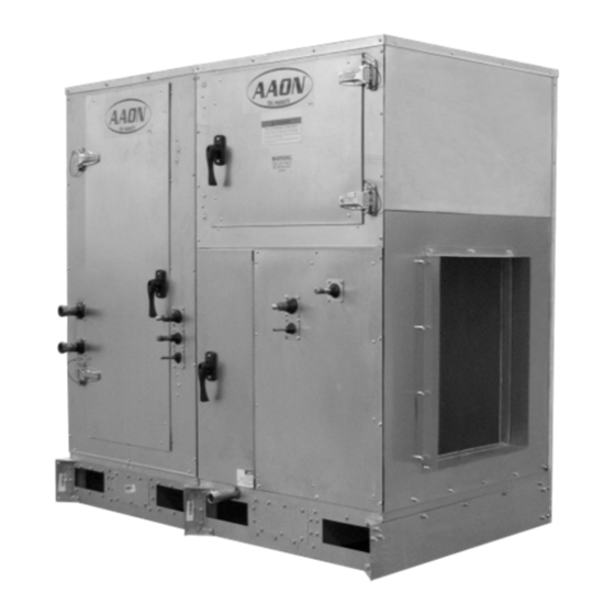
AAON SB series Installation Operation & Maintenance (72 pages)
Vertical Self-Contained Units
Brand:
AAON
| Category:
Fan
| Size: 3.96 MB
Table of Contents
Table of Contents
3
AAON SB Series Features and Options Introduction
6
Safety
7
SB Series Feature String Nomenclature
14
General Information
18
Codes and Ordinances
18
Receiving Unit
19
Storage
19
Direct Expansion (DX) Systems
19
Figure 1 - Lockable Handle
19
Wiring Diagrams
20
Condensate Drain Pans
20
Installation
21
Locating the Unit
21
Table 1 - SB Series Clearances
21
Table 2 - Clearances for Coil Pull
21
Figure 2 - SB Series
21
Lifting and Handling the Unit
22
Unit Assembly
22
Figure 3 - SB Series Unit Orientation
22
Figure 4 - SB Schematic with (1) Exhaust Fan, (2) Energy Recovery, (3) Air Handler, and
23
Figure 5 - Connect Sections
23
Figure 6 - Bar Clamp
23
Figure 7 - Flange Overlap
23
Figure 8 - Self-Tapping Screw
23
Figure 9 - Strap Types
24
Figure 10 - Low Voltage Quick Connect
24
Refrigerant-To-Water Heat Exchanger Water Piping
25
Figure 11 - Ship Split Sections
25
Table 3 - Glycol Concentration Freezing Points (Metric)
27
Table 4 - Glycol Concentration Freezing Points (Imperial)
27
Table 5 - Condenser Water Connections
27
Table 6 - Water Connection Locations
28
Figure 12- Water Connections for Water-Source Heat Pumps
28
Electrical
29
Table 7 - Nameplate Voltage Markings & Tolerances
29
Figure 13 - Electrical Connection
30
Table 8 - Control Wiring
32
Duct Connection
33
Condensate Drain Piping
33
Table 9 - 35 KAIC Fuse Sizing
33
Table 10 - 65 KAIC Fuse Sizing
33
Figure 14 - Drain Trap
33
Waterside Economizer
34
Table 11 - Drain Trap Dimensions (Metric)
34
Table 12 - Drain Trap Dimensions (Imperial)
34
Heating Coils
35
Energy Recovery Units
35
Table 13 -Min and Max Water Pressure and Temps
35
Figure 15 - Energy Recovery Wheel
36
Figure 16 - Cross Section of Air Seal Structure
37
Figure 17 - Lifting Hole Locations
38
Figure 18 - Diameter Seal Adjustment
40
Figure 19 - Avoid Racking of Cassette Frame
41
Figure 20 - Diameter Seal Adjustment
42
Figure 21 - Hub Seal Adjustment
42
Figure 22 - Segment Retainer
42
Figure 23 - Segment Installation
43
Startup
44
Figure 24 - Belt Replacement
44
Supply Fans
45
Fan Air Flow Adjustment
45
Filters
45
Figure 25 - Typical Wiring Diagram with EC Motor
45
Figure 26 - Shows the Jumper that Is to be Removed (Jumped between S1 and S2)
45
Adjusting Refrigerant Charge
46
Freeze Stat Startup
47
Table 14 - Acceptable Water-Cooled Refrigeration Circuit Values (Metric)
47
Table 15 - Acceptable Water-Cooled Refrigeration Circuit Values (Imperial)
47
Table 16 - Minimum Airflow and Room Areas
48
Table 17 - Minimum Airflow and Room Areas (Continued)
49
Table 18 - R-454BA Refrigerant Temperature-Pressure Chart (Metric)
50
Table 19 - R-454B Refrigerant Temperature-Pressure Chart (Imperial)
51
Operation
52
Refrigerant Detection System
52
Packaged DX Cooling Operation and Control
52
Electric Heating Operation
52
Steam or Hot Water Preheating Operation
52
Maintenance
52
Refrigerant Removal and Evacuation
53
DX Cooling
54
Condensate Drain Pans
54
E-Coated Coil Cleaning
54
Supply Fans
56
Filter Replacement
56
Phase and Brownout Protection Module
57
Filter Information
59
Table 20 - 3-5 Ton (B Cabinet) Pre and Unit Filters
59
Table 21 - 6-10 Ton (C Cabinet) Pre and Unit Filters
59
Table 22 - 14-18 Ton (D Cabinet) Pre and Unit Filters
59
Table 23 - 3-5 Ton (B Cabinet) Mixing Box Filters
60
Table 24 - 6-10 Ton (C Cabinet) Mixing Box Filters
60
Table 25 - 14-18 Ton (D Cabinet) Mixing Box Filters
61
Apendix a - Heat Exchanger Corrosion Resistance
64
Maintenance Log (E-Coated Coil)
70
(Lv J000301)
72
Advertisement
AAON SB series Installation Operation & Maintenance (64 pages)
Vertical Self-Contained Units
Brand:
AAON
| Category:
Air Conditioner
| Size: 4.41 MB
Table of Contents
Table of Contents
3
AAON SB Series Features and Options Introduction
6
Safety
7
SB Series Feature String Nomenclature
12
General Information
16
Codes and Ordinances
16
Receiving Unit
17
Storage
17
Direct Expansion (DX) Systems
17
Figure 1 - Lockable Handle
17
Wiring Diagrams
18
Condensate Drain Pans
18
Installation
19
Locating the Unit
19
Table 1 - SB Series Clearances
19
Figure 2 - SB Series
19
Lifting and Handling the Unit
20
Unit Assembly
20
Figure 3 - SB Series Unit Orientation
20
Figure 4 - SB Schematic with (1) Exhaust Fan, (2) Energy Recovery, (3) Air Handler, and
21
Figure 5 - Connect Sections
21
Figure 6 - Bar Clamp
21
Figure 7 - Flange Overlap
21
Figure 8 - Self-Tapping Screw
21
Refrigerant-To-Water Heat Exchanger Water Piping
22
Figure 9 - Strap Types
22
Figure 10 - Low Voltage Quick Connect
22
Table 2 - Glycol Freezing Points
24
Table 3 - Condenser Water Connections
25
Table 4 - Water Connection Locations
25
Figure 11- Water Connections for Water-Source Heat Pumps
25
Electrical
26
Figure 12 - Electrical Connection
26
Duct Connection
29
Condensate Drain Piping
29
Table 5 - Control Wiring
29
Waterside Economizer
30
Table 6 - Drain Trap Dimensions
30
Figure 13 - Drain Trap
30
Heating Coils
31
Energy Recovery Units
31
Initial Mechanical Check and Setup
32
Figure 14 - Energy Recovery Wheel
32
Figure 15 - Cross Section of Air Seal Structure
32
Routine Maintenance and Handling
33
Figure 16 - Lifting Hole Locations
33
Cleaning
34
Wheel Drive Components
35
Startup Procedure
35
Figure 17 - Avoid Racking of Cassette Frame
35
Service
36
Figure 18 - Diameter Seal Adjustment
36
Figure 19 - Hub Seal Adjustment
36
Figure 20 - Segment Retainer
37
Figure 21 - Segment Installation
37
Figure 22 - Belt Replacement
38
Startup
39
Supply Fans
39
Fan Air Flow Adjustment
39
Figure 23 - SB Series Supply Fan
39
Figure 24- Typical Wiring Diagram with EC Motor
39
Filters
40
Adjusting Refrigerant Charge
40
Figure 25 - Shows the Jumper that Is to be Removed (Jumped between 9 and GS)
40
Figure 26 - Potentiometer
40
Table 7 - Acceptable Water-Cooled Refrigeration Circuit Values
41
Freeze Stat Startup
42
Table 8 - R-410A Refrigerant Temperature-Pressure Chart
43
Operation
44
Packaged DX Cooling Operation and Control
44
Electric Heating Operation
44
Steam or Hot Water Preheating Operation
44
Maintenance
44
DX Cooling
45
Condensate Drain Pans
45
E-Coated Coil Cleaning
45
Supply Fans
47
Phase and Brownout Protection Module
48
Filter Replacement
50
Replacement Parts
50
AAON Longview Product Support
50
Filter Information
51
Table 9 - 3-5 Ton (B Cabinet) Pre and Unit Filters
51
Table 10 - 6-10 Ton (C Cabinet) Pre and Unit Filters
51
Table 11 - 14-18 Ton (D Cabinet) Pre and Unit Filters
51
Table 12- 3-5 Ton (B Cabinet) Mixing Box Filters
52
Table 13 - 6-10 Ton (C Cabinet) Mixing Box Filters
53
Table 14 - 14-18 Ton (D Cabinet) Mixing Box Filters
53
Appendix A - Heat Exchanger Corrosion Resistance
54
Table 15 - Condenser Water Connections Updated
60
(Acp 31227)
64
Advertisement
Related Products
AAON SB-003
AAON SB-005
AAON SB-006
AAON SB-007
AAON SB-009
AAON SB-010
AAON SB-013
AAON SB-016
AAON SB-018
AAON SB014
AAON Categories
Controller
Control Unit
Air Handlers
Heat Pump
Air Conditioner
More AAON Manuals
Login
Sign In
OR
Sign in with Facebook
Sign in with Google
Upload manual
Upload from disk
Upload from URL