Sign In
Upload
Manuals
Brands
AAON Manuals
Chiller
LZ Series
AAON LZ Series Manuals
Manuals and User Guides for AAON LZ Series. We have
1
AAON LZ Series manual available for free PDF download: Installation Operation & Maintenance
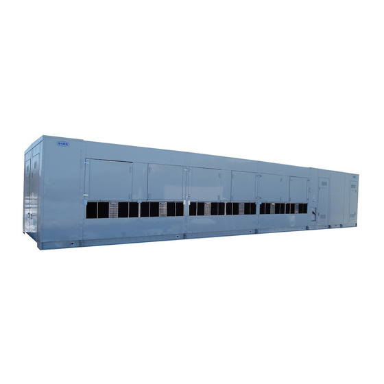
AAON LZ Series Installation Operation & Maintenance (104 pages)
Chillers and Outdoor Mechanical Rooms
Brand:
AAON
| Category:
Chiller
| Size: 4 MB
Table of Contents
Table of Contents
3
Codes and Ordinances
19
Receiving Unit
19
Storage
20
Outdoor Mechanical Room
20
Wiring Diagrams
21
General Maintenance
21
Chiller Primary Pumping
21
Chiller Primary/Secondary Pumping
22
Condensing Boilers
22
Makeup Water
23
Compression Tank
23
Figure 1 - Backflow Preventer
23
Pressure Relief Valve
24
Automatic Air Vent
24
Dual Pumps
24
Pressure Gauges and Thermometers
24
Figure 2 - Pressure Relief Valve
24
Table 1 - Service Clearances
25
Pipe Insulation
25
Outdoor Mechanical Room Placement
25
Curb and Steel Mount Installation
25
Figure 3 - Curb Mounting with Dimensions
26
Figure 4 - Curb End Detail
26
Figure 5 - Steel Mounting Rail with Dimensions
26
Figure 6 - Concrete Pad Mounting with Dimensions
27
Figure 7 - LZ Base
27
Lifting and Handling
28
Figure 8 - Lifting Points
28
Vestibule Exhaust Fan
29
Figure 9 - LZ Series Example Lifting Detail
29
Figure 10 - Vestibule Exhaust Fan
29
Water Connection
30
Figure 11 - Water Pipe Flashing Installation
30
Temporary Drain - Evaporative Condenser
31
Access Doors
31
End Flashing Installation
31
Figure 12 - Temporary Drain Components
31
Figure 13 - Factory Supplied End Flashings
31
Boiler Gas Connection
32
Boiler Air Intake / Vent Piping
32
Table 2 - Unit Gas Pipe Information, Feature B4 = A-J
33
Table 3 - Unit Gas Pipe Information, Feature B4 = K-N
34
Sidewall Direct Boiler Venting
35
Figure 14 - Sidewall Vent Shipping Cover Removal
35
Figure 15 - Sidewall Vent Plate Installation
35
Figure 16 - Typical Air Intake Piping
35
Figure 17 - Typical Flue Vent Piping
36
Vertical Direct Boiler Venting
37
Figure 18 - Sidewall Vent Base
37
Figure 19 - Sidewall Vent Cap
37
Figure 20 - Roof Air Intake and Vent Piping Shipping Covers
37
Figure 21 - Typical Vertical Air Intake Piping
38
Figure 22 - Correct Joint Connection
39
Figure 23 - Incorrect Joint Connection
39
Figure 24 - Typical Vertical Vent Piping
40
Figure 25 - Vertical Termination of Air Intake and Vent Piping
40
Boiler Condensate Drain
41
Split Unit Assembly
41
Unit Mounting Isolation
41
Low Ambient Operation
41
Table 4 - Nameplate Voltage Markings
42
Electrical
42
Table 5- Tandem Circuited Variable Speed Compressor VFD Frequency Range
44
Variable Speed Compressors
44
Figure 26 - Evaporative-Condensed Chiller Section Layout
45
Table 6 - Air-Cooled Condenser Fan Pitch
47
Table 7 - Evaporative-Condensed Chiller Fan Pitch
47
Condenser Fan Pitch Adjustment
47
Figure 27 - Fan with the HUB on the Top and RET on the Bottom
48
Figure 28 - Bushing Mount Location
48
Figure 29 - RET with Pin in Groove 4
48
Figure 30 - Fan HUB and RET Castings
48
Table 8 - Condenser Fan Pin Location (Bushing Mount)
49
Figure 31 - Pitch Insert
49
Table 9 - Condenser Fan Pin Location (Rotation Direction)
49
Table 10 - Fan Assembly Bushing Torque Specifications
50
Boiler System Startup
50
Boiler Sequence of Operations
51
General
51
Refrigerant Suction Line Filter
51
Figure 32 - Replaceable Core Filter Driers
52
Table 11 - Filter Drier Maximum Pressure Drop
52
Suction Filter Removal Instructions
52
Refrigerant Liquid Line Filter Driers
52
Evaporator/Heat Exchangers
53
Adjusting Refrigerant Charge
53
Table 12 - Acceptable Refrigeration Circuit Values
54
Table 13 - R-134A Refrigerant Temperature-Pressure Chart
55
Table 14 - R-410A Refrigerant Temperature-Pressure Chart
56
Air-Cooled Condenser
57
E-Coated Coil Cleaning
57
Lubrication
57
Microchannel Coil Cleaning
59
Evaporative-Condensed Chiller
61
Severe Operating Conditions Service
62
Safety
62
Performance
62
Figure 33 - Proper Unit Location
62
Figure 34 - Improper Unit Locations
62
Warranties
63
Condenser Tube Inspection
63
Freeze Protection
63
Recirculating Water System
63
Startup
63
Cleanliness
63
Storage
63
Pump Operation
64
Running
64
Condenser Fan Motors
64
Water Make up Valve
64
Water Treatment System
65
Sequence of Operation for LZ Series Units Without Diagnostics
65
Figure 35 - Water Makeup Valve
65
Sequence of Operation for LZ Series Units with Diagnostics
66
Pump Maintenance
67
Fan Motor Maintenance
67
Access Doors
67
Figure 36 - Evaporative Condenser Access Door
67
Bearings - Lubrication
68
Recommended Monthly Inspection
68
Mist Eliminators
68
Air Inlet
68
Stainless Steel Base Pan
68
Propeller Fans and Motors
68
Recommended Annual Inspection
68
Cleaning
68
Water Quality
69
Table 15 - Recirculating Water Quality Guidelines
69
Mechanical Cleaning
70
Service
70
Replacement Parts
70
Water Pressure Reducing Valve
71
Water Pressure Relief Valve
73
Automatic Air Vent Valves
73
Pumps - Installation and Operating Instructions
75
Pump Piping - General
77
Pump Operation
77
General Care
78
Dual Pump Specific Information
80
Horizontal and Vertical Expansion Tanks
85
Suction Guides
86
Glycol Auto Fill Unit
87
Flo-Trex Combination Valve
89
Advertisement
Advertisement
Related Products
AAON LF Series
AAON LN Series
AAON Categories
Controller
Control Unit
Air Handlers
Heat Pump
Air Conditioner
More AAON Manuals
Login
Sign In
OR
Sign in with Facebook
Sign in with Google
Upload manual
Upload from disk
Upload from URL