
Related Manuals for Acer ASPIRE 5334


Summary of Contents for Acer ASPIRE 5334
- Page 1 Aspire 5334/5734Z Series Service Guide Service guide files and updates are available on the ACER/CSD web; for more information, please refer to http://csd.acer.com.tw PRINTED IN TAIWAN...
-
Page 2: Revision History
Revision History Aspire 5334 Series Please refer to the table below for the updates made on service guides. Date Chapter Updates... - Page 3 Copyright Copyright © 2010 by Acer Incorporated. All rights reserved. No part of this publication may be reproduced, transmitted, transcribed, stored in a retrieval system, or translated into any language or computer language, in any form or by any means, electronic, mechanical, magnetic, optical, chemical, manual or otherwise, without the prior written permission of Acer Incorporated.
- Page 4 Conventions The following conventions are used in this manual: SCREEN MESSAGES NOTE WARNING CAUTION IMPORTANT Denotes actual messages that appear on screen. Gives bits and pieces of additional information related to the current topic. Alerts you to any damage that might result from doing or not doing specific actions.
- Page 5 Preface Before using this information and the product it supports, please read the following general information. This Service Guide provides you with all technical information relating to the BASIC CONFIGURATION decided for Acer's "global" product offering. To better fit local market requirements and enhance product competitiveness, your regional office MAY have decided to extend the functionality of a machine (e.g.
-
Page 7: Table Of Contents
System Specifications Features ............1 Optical Media Drive . - Page 8 Table of Contents Removing the Mainboard ......... .74 Removing the RTC Battery .
- Page 9 Undetermined Problems ..........136 Post Codes .
- Page 10 Table of Contents...
-
Page 11: System Specifications
• Genuine Windows® 7 Home Basic 64-bit Platform Aspire 5334 • Intel® Celeron® processor T3100/T3000 (1 MB L2 cache, 1.80/1.90 GHz, 800 MHz FSB, 35 W), T1600/T1700 (1 MB L2 cache, 1.66/1.83 GHz, 667 MHz FSB, 35 W), supporting Intel® 64 architecture •... -
Page 12: Optical Media Drive
One built-in mono speaker • Built-in microphone • MS-Sound compatible Storage subsystem Aspire 5334/5734Z • Hard disk drive: 160/250/320/500/640 GB or larger Aspire 5734Z • Multi-in-1 card reader, supporting Secure Digital™ (SD), MultiMediaCard (MMC), Memory Stick™ (MS), Memory Stick PRO™ (MS PRO), xD-Picture Card™ (xD) Optical Media Drive •... -
Page 13: Special Keys And Controls
Power subsystem ACPI 3.0 CPU power management standard: supports Standby and Hibernation power-saving modes Adapter: • 3-pin 65 W AC adapter: • 108 (W) x 46 (D) x 29.5 (H) mm (4.25 x 1.81 x 1.16 inches) • 225 g (0.49 lbs.) with 180 cm DC cable Battery: •... -
Page 14: Optional Items
Security • McAfee® Internet Security Suite Trial • MyWinLocker® (except China, Hong Kong) Multimedia • Cyberlink® PowerDVD™ • NTI Media Maker™ Gaming • Oberon GameZone (except US, Canada, Hong Kong, Korea) • WildTangent® (US, Canada only) Communication and ISP • Acer Crystal Eye •... -
Page 15: System Block Diagram
System Block Diagram Chapter 1... -
Page 16: Your Acer Notebook Tour
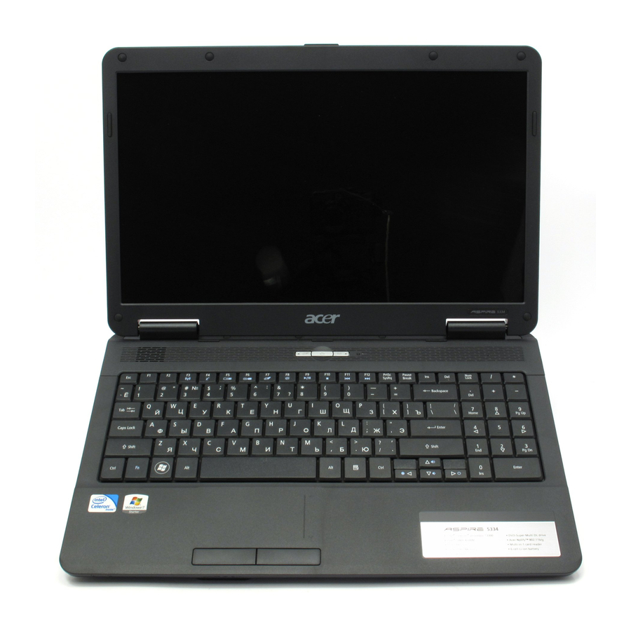
Your Acer Notebook tour Front View Icon Item Acer Crystal Eye Web camera for video communication webcam (for selected models). Display screen Also called Liquid-Crystal Display (LCD), displays computer output. Speaker Delivers audio output. Keyboard For entering data into your computer. Touchpad Touch-sensitive pointing device which functions like a computer mouse. -
Page 17: Closed Front View
Icon Closed Front View Aspire 5734Z model only Icon Left View Icon Chapter 1 Item Click buttons (left The left and right buttons function like the left and right) and right mouse buttons. Palmrest Comfortable support area for your hands when you use the computer. - Page 18 Icon Item Ethernet (RJ-45) Connects to an Ethernet 10/100-based port network. External display Connects to a display device (VGA) port (e.g. external monitor, LCD projector). USB 2.0 ports Connect to USB 2.0 devices (e.g. USB mouse, USB camera). Microphone-in Accepts input from external microphones. jack Headphones/ Connects to audio line-out devices...
-
Page 19: Right View
Right View Item Optical drive Optical disk access indicator Optical drive eject button Emergency eject hole Kensington lock slot Bottom View Icon Chapter 1 Description Internal optical drive; accepts CDs or DVDs. Lights up when the optical drive is active. Ejects the optical disk from the drive. -
Page 20: Indicators
Icon Indicators The computer has several easy-to-read status indicators. The front panel indicators are visible even when the computer cover is closed. Icon Power Battery Num Lock Caps Lock Item Battery release Releases the battery for removal. latch Memory Houses the computer's main memory. compartment Hard disk bay Houses the computer's hard disk (secured... -
Page 21: Touchpad Basics
TouchPad Basics The following items show you how to use the TouchPad: • Move your finger across the TouchPad (1) to move the cursor. • Press the left (2) and right (3) buttons located beneath the TouchPad to perform selection and execution functions. -
Page 22: Using The Keyboard
Using the Keyboard The keyboard has full-sized keys and an embedded numeric keypad, separate cursor, lock, Windows, function and special keys. Lock Keys and embedded numeric keypad The keyboard has two lock keys which you can toggle on and off. Lock key Caps Lock When Caps Lock is on, all alphabetic characters typed are in uppercase. -
Page 23: Windows Keys
Windows Keys The keyboard has two keys that perform Windows-specific functions. Windows key Pressed alone, this key has the same effect as clicking on the Windows Start button; it launches the Start menu. It can also be used with other keys to provide a variety of functions: <... -
Page 24: Hot Keys
Hot Keys The computer employs hotkeys or key combinations to access most of the computer’s controls like screen brightness, volume output and the BIOS utility. To activate hot keys, press and hold the <Fn> key before pressing the other key in the hotkey combination. Hotkey Icon <Fn>... -
Page 25: Hardware Specifications And Configurations
Hardware Specifications and Configurations Processor Item • • Type Intel Mobile PDC uPGA -478 Core Logic Mobile Intel® GL40/GM45 Express Chipset CPU Package Micro uPGA-478 Package Power 65 Watts On-die Cache 4MB L2 cache Front Side Bus 667/800/1066MHz Processor Specifications Item Cores Speed... - Page 26 BIOS Item BIOS vendor BIOS Version BIOS ROM type Features System Memory Item Memory controller Memory size DIMM socket number Supports memory size per socket Supports maximum memory size Supports DIMM type Supports DIMM Speed Supports DIMM voltage Specification Insyde BIOS V0.06-T02 Flash •...
- Page 27 Memory Combinations Slot 1 512MB 512MB 512MB 1024MB 1024MB 1024MB 1024MB 2048MB 2048MB 2048MB 2048MB NOTE: Above table lists some system memory configurations. You may combine DIMMs with various capacities to form other combinations. On above table, the configuration of slot 1 and slot 2 could be reversed.
- Page 28 Hard Disk Drive Interface Item Vendor & Model Seagate Name ST9500325AS ST9250315AS Capacity (MB) 500, 250 Bytes per sector Data heads 4, 2 Drive Format Disks 2, 1 Spindle speed 5400 (RPM) Buffer size 8 MB Interface SATA Internal transfer rate (Mbits/sec, max) I/O data transfer...
- Page 29 Super-Multi Drive Module Item Specification Vendor & model name HLDS GT20N Performance With CD Diskette Specification Transfer rate (MB/sec) Sustained: 3,600 KB/s (24x) max. Buffer Memory 2 MB Interface SATA Applicable disc DVD-ROM: formats 4.7GB (Single Layer) 8.5GB (Dual Layer) DVD-R: 3.95GB (Ver.
- Page 30 Power and Keyboard Controller Item Controller Total number of keypads Windows logo key Hotkeys Battery Item Vendor & model name Battery Type Pack capacity Normal Voltage Package configuration LCD 17” Item Vendor/model name Screen Diagonal (mm) Display Area (mm) Display resolution (pixels) Pixel Pitch Display Mode Typical White Luminance (cd/m...
- Page 31 LCD Display Supported Resolution Resolution 640x480p/60Hz 4:3 720x480p/60Hz 4:3 720x480p/60Hz 16:9 1280x720p/60Hz 16:9 1440x480i/60Hz 4:3 1440x480i/60Hz 16:9 USB Port Item USB Compliance Level OHCI Number of USB Ports Location AC Adapter Item Input rating Maximum input AC current Inrush current Efficiency Chapter 1 18 bits...
- Page 32 System Power Management Item Mech. Off (G3) Soft Off (G2/S5) Working (G0/S0) Sleeping State (S3) Sleeping State (S4) Specification Al devices in the system are turned off completely. OS initiated shutdown. All devices in the system are turned off completely. Individual devices such as the CPU and hard disc may be power managed in this state.
-
Page 33: System Utilities
System Utilities BIOS Setup Utility The BIOS Setup Utility is a hardware configuration program built into your computer’s BIOS (Basic Input/ Output System). Your computer is already properly configured and optimized, and you do not need to run this utility. However, if you encounter configuration problems, you may need to run Setup. -
Page 34: Hm52-Mv Intel Bios
HM52-MV Intel BIOS Information The Information screen displays a summary of your computer hardware information. Information Main Security C P U T y p e C P U T y p e C P U S p e e d C P U S p e e d I D E 0 M o d e l N a m e : I D E 0 M o d e l N a m e :... -
Page 35: Main
Main The Main screen allows the user to set the system time and date as well as enable and disable boot option and recovery. Information Main S y s t e m Ti m e : S y s t e m Ti m e : S y s t e m D a t e : S y s t e m D a t e : To t a l M e m o r y :... -
Page 36: Security
Security The Security screen contains parameters that help safeguard and protect your computer from unauthorized use. Information Main S u p e r v i s o r P a s s w o r d I s : S u p e r v i s o r P a s s w o r d I s : U s e r P a s s w o r d I s : U s e r P a s s w o r d I s : S A T A P o r t 0 D i s k S t a t u s :... -
Page 37: Removing A Password
Setting a Password Follow these steps as you set the user or the supervisor password: Use the ↑ and ↓ keys to highlight the Set Supervisor Password parameter and press the Enter key. The Set Supervisor Password box appears: Type a password in the “Enter New Password” field. The password length can not exceed 8 alphanumeric characters (A-Z, a-z, 0-9, not case sensitive). -
Page 38: Changing A Password
Changing a Password Use the ↑ and ↓ keys to highlight the Set Supervisor Password parameter and press the Enter key. The Set Password box appears. Type the current password in the Enter Current Password field and press Enter. Type a password in the Enter New Password field. Retype the password in the Confirm New Password field. -
Page 39: Boot
Boot This menu allows the user to decide the order of boot devices to load the operating system. Bootable devices includes the USB diskette drives, the onboard hard disk drive and the DVD drive in the module bay. Select Boot Devices to select specific devices to support boot. Information Main Security... -
Page 40: Exit
Exit The Exit screen allows you to save or discard any changes you made and quit the BIOS Utility. Information Main Security E x i t S a v i n g C h a n g e s E x i t S a v i n g C h a n g e s E x i t D i s c a r d i n g C h a n g e s E x i t D i s c a r d i n g C h a n g e s L o a d S e t u p D e f a u l t s... -
Page 41: Bios Flash Utilities
BIOS Flash Utilities The BIOS flash memory update is required for the following conditions: • New versions of system programs • New features or options • Restore a BIOS when it becomes corrupted. Use the Flash utility to update the system BIOS flash ROM. NOTE: If you do not have a crisis recovery diskette at hand, then you should create a Crisis Recovery Diskette before you use the Flash utility. -
Page 42: Dos Flash Utility
DOS Flash Utility Perform the following steps to use the DOS Flash Utility: Press F2 during boot to enter the Setup Menu. Select Boot Menu to modify the boot priority order, for example, if using USB HDD to Update BIOS, move USB HDD to position 1. - Page 43 In flash BIOS, the message Please do not remove AC Power Source displays. NOTE: If the AC power is not connected, the following message displays. Plug in the AC power to continue. Flash is complete when the message Flash programming complete displays. Chapter 2...
-
Page 44: Winflash Utility
WinFlash Utility Perform the following steps to use the WinFlash Utility: Double-click the WinFlash executable. Click OK to begin the update. A progress screen displays. Chapter 2... -
Page 45: Remove Hdd/Bios Password Utilities
Remove HDD/BIOS Password Utilities This section provides you with details about removing HDD/BIOS password: Remove HDD Password: If you key in the wrong HDD password three times, an error is generated. To reset the HDD password, perform the following steps: After the error is displayed, select the Enter Unlock Password option on the screen. - Page 46 Removing BIOS Passwords: To clear the User or Supervisor passwords, open the RAM door and use a metal instrument to short the J1 jumper. Cleaning BIOS Passwords To clean the User or Supervisor passwords, perform the following steps: From a DOS prompt, execute clnpwd.exe Press 1 or 2 to clean the desired password shown on the screen.
-
Page 47: Using Boot Sequence Selector
Using Boot Sequence Selector The Boot Sequence Selector allows the boot order to be changed without accessing the BIOS. To use Boot Sequence Selector, perform the following steps: Enter into DOS. Execute BS.exe to display the usage screen. Select the desired boot sequence by entering the corresponding sequence. For example, enter BS2 to change the boot sequence to HDD | CD ROM | LAN | Floppy. -
Page 48: Using Dmitools
Using DMITools The DMI (Desktop Management Interface) Tool copies BIOS information to EEPROM to be used in the DMI pool for hardware management. When the BIOS displays Verifying DMI pool data it is checking that the table correlates with the hardware before sending to the operating system (Windows, etc.). -
Page 49: Using The Lan Mac Eeprom Utility
Using the LAN MAC EEPROM Utility You can use the MAC.BAT utility to write the MAC.CFG file to the EEPROM under DOS mode. Use a text editor (for example: Notepad) to open the MAC.CFG file. You can see the MAC.CFG contents as below: WriteData = ‘001122334455' StartAddr=7A... -
Page 50: Creating A Usb Flash Crisis Disk
Creating a USB Flash Crisis Disk Plug in the USB flash disk. Select the Fast Format option and click Start. Then click Next. Click Format and then Exit to complete the operation. Chapter 2... - Page 51 Copy the PAWF5x64.fd file to the USB flash disk root directory. NOTE: Do not place any other *.fd files to the USB flash disk root directory. Using the crisis disk Plug in the USB Flash Disk without AC plug. Press Fn +esc keys and hold them down, then plug in AC power. The power button flashes orange. Press power button and the system will enter crisis mode to flash the BIOS.
- Page 52 Chapter 2...
-
Page 53: Machine Disassembly And Replacement
Machine Disassembly and Replacement IMPORTANT: The outside housing and color may vary from the mass produced model. This chapter contains step-by-step procedures on how to disassemble the notebook computer for maintenance and troubleshooting. Disassembly Requirements To disassemble the computer, you need the following tools: Wrist grounding strap and conductive mat for preventing electrostatic discharge •... -
Page 54: Pre-Disassembly Instructions
Pre-disassembly Instructions Before proceeding with the disassembly procedure, make sure that you do the following: 1. Turn off the power to the system and all peripherals. 2. Unplug the AC adapter and all power and signal cables from the system. 3. -
Page 55: External Module Disassembly Process
External Module Disassembly Process IMPORTANT: The outside housing and color may vary from the mass produced model. External Modules Disassembly Flowchart The flowchart below gives you a graphic representation of the external module disassembly sequence and instructs you on the components that need to be removed during servicing. For example, if you want to remove the keyboard, you must first remove the switch board. -
Page 56: Removing The Battery Pack
Removing the Battery Pack 1. Turn computer over. Slide the battery lock in the direction shown. 2. Slide and hold the battery release latch to the release position (1), then lift out the battery pack from the main unit (2). NOTE: The battery has been highlighted with a yellow oval as shown in the above image. -
Page 57: Removing The Sd Dummy Card
Removing the SD Dummy Card 1. Push the SD dummy card all the way in to eject it. 2. Pull it out from the slot. Chapter 3... -
Page 58: Removing The Lower Covers
Removing the Lower Covers 1. See “Removing the Battery Pack” on page 46. 2. Remove the three (3) screws securing the Memory and HDD Covers. Memory Cover Step Lower Covers M2.5*8 3. Remove the HDD cover as shown. 4. Carefully open the Memory Cover. Size Quantity Cover... -
Page 59: Removing The Optical Drive Module
Removing the Optical Drive Module 1. See “Removing the Lower Covers” on page 48. 2. Remove the screw securing the ODD module. Step ODD Module M2.5*8 3. Insert a suitable tool into the access slot in the battery bay as shown. Gently lever the ODD module out of the chassis. - Page 60 5. Remove the ODD bezel by rotating the top edge downward and pulling it clear of the module. 6. Remove the two (2) screws securing the ODD bracket and remove the ODD bracket from the optical disk drive module. Step Size Quantity Screw Type...
-
Page 61: Removing The Dimm Modules
Removing the DIMM Modules 1. See “Removing the Lower Covers” on page 48. 2. Push out the release latches on both sides of the DIMM socket to release the DIMM module. 3. Remove the DIMM module. 4. Repeat steps for the second DIMM module if present. Chapter 3... -
Page 62: Removing The Wlan Module
Removing the WLAN Module 1. See “Removing the Lower Covers” on page 48. 2. Remove the adhesive tape securing the Antenna cables in place. 3. Disconnect the antenna cables from the WLAN Board. NOTE: Cable placement is Black to the MAIN terminal (upper) and White to the AUX terminal (lower). Chapter 3... - Page 63 4. Move the antenna away and remove the two (2) screws to release the WLAN Board. Step Size Quantity Screw Type WLAN Module M2*3 5. Detach the WLAN Board from the WLAN socket. NOTE: When reattaching the antennas, ensure the cables are tucked into the chassis to prevent damage. Chapter 3...
- Page 64 6. Remove two (2) screws from the WLAN bracket. Step Size Quantity Screw Type WLAN Module M2*3 7. Lift the WLAN bracket clear of the chassis. Chapter 3...
-
Page 65: Removing The Hard Disk Drive Module
Removing the Hard Disk Drive Module 1. See “Removing the Lower Covers” on page 48. 2. Using the pull-tab, slide the HDD Module in the direction of the arrow to disconnect the interface. 3. Lift the HDD Module clear of the HDD bay. NOTE: To prevent damage to device, avoid pressing down on it or placing heavy objects on top of it. - Page 66 4. Remove the four (4) screws (two each side) securing the hard disk to the carrier. Step Size Quantity Screw Type HDD Carrier M3*3 5. Remove the HDD from the carrier. Chapter 3...
-
Page 67: Removing The Switch Cover
Removing the Switch Cover CAUTION: Using metal tools to remove the Switch Cover may cause damage to the outer casing. The use of plastic tools or fingers is recommended to remove the Switch Cover. 1. See “Removing the Battery Pack” on page 46. 2. -
Page 68: Removing The Keyboard
Removing the Keyboard 1. See “Removing the Switch Cover” on page 57. 2. Pry up the centre of the Keyboard and rotate it upward away from the Upper Cover. 3. Turn the keyboard over on to the TouchPad area to expose the FFC connector. 4. -
Page 69: Main Unit Disassembly Process
Main Unit Disassembly Process Main Unit Disassembly Flowchart Remove Remove Left Speaker Power Board Module Screw List Step LCD Module M2.5*8 LCD Module M2.5*8 Upper Cover M2.5*8 Upper Cover M2.5*8 Power Board M2*3 Left Speaker Module M2*3 Right Speaker Module M2*3 TouchPad Bracket M2*3... -
Page 70: Removing The Lcd Module
Removing the LCD Module 1. See “Removing the Keyboard” on page 58. 2. Turn the computer over. Remove the two (2) securing screws from the bottom of the chassis. Step LCD Module M2.5*8 3. Remove the Antenna Cables from the cable channel as shown. Ensure that the cables are free from all cable clips. - Page 71 4. Stand the computer on the LCD Panel and pull the Antenna cables completely through the chassis. 5. Disconnect the LVDS cable from the Mainboard. 6. Remove the cable from the cable channel. Chapter 3...
- Page 72 7. Remove the white Antenna cable from the cable channel. Ensure that the cable is completely free of the retaining clips all the way to the hinge well. 8. Remove the microphone cable. Disconnect the microphone cable on the upper cover. Peel back the foil tab on the microphone assembly.
- Page 73 10. Press the left side Hinge Cover inward, as shown, and lift to remove the cover from the chassis. 11. Repeat the process for the right side Hinge Cover. 12. Remove the four (4) securing screws (two each side) from the LCD module. Step Size Quantity...
- Page 74 14. Lift the LCD Module clear of the Upper Cover. Chapter 3...
-
Page 75: Removing The Upper Cover
Removing the Upper Cover 1. See “Removing the LCD Module” on page 60. 2. Turn the computer over. Remove the eleven (11) screws on the bottom panel. Step Upper Cover M2.5*8 3. Turn the computer over. Remove the three (3) screw caps at the rear of the Upper Cover as shown. Chapter 3 Size Quantity... - Page 76 4. Disconnect the following three (3) cables from the Mainboard. 5. Disconnect the speaker cable as shown. Chapter 3...
- Page 77 6. Release the locking latch on the power board and disconnect the FFC cable as shown. 7. Release the locking latch on the touchpad FFC and disconnect as shown. NOTE: Avoid pulling on cables directly to prevent damage to the connectors. NOTE: Use the pull-tabs on FFCs whenever available to prevent damage.
- Page 78 8. Remove the nine (9) screws on the top panel. Step Size Quantity Screw Type Upper Cover M2.5*8 9. Starting at the front right side of the cover, pry apart the Upper and Lower Covers as shown. Work along the front edge of the casing to the left as shown, then lift the Upper Cover clear of the Lower Cover.
-
Page 79: Removing The Power Board
Removing the Power Board 1. See “Removing the Upper Cover” on page 65. 2. Locate the Power Board on the Upper Cover as shown. 3. Remove the two (2) screws securing the Power Board to the Upper Cover. Step Power Board M2*3 4. -
Page 80: Removing The Left Speaker Module
Removing the Left Speaker Module 1. See “Removing the Upper Cover” on page 65. 2. Locate the Left Speaker Module on the Upper Cover as shown. 3. Remove the Speaker cable from the cable channel. Ensure that the cable is free from all cable clips. 4. - Page 81 5. Lift the Speaker clear of the Upper Cover, left side first as shown. Chapter 3...
-
Page 82: Removing The Touchpad Bracket
Removing the TouchPad Bracket IMPORTANT: The TouchPad Board cannot be removed individually. To replace the TouchPad Board, replace the entire Upper Cover. 1. See “Removing the Upper Cover” on page 65. 2. Lift the FFC to detach the adhesive securing the cable to the Upper Cover. 3. - Page 83 4. Remove the two (2) screws from TouchPad bracket. Step Size Quantity Screw Type TouchPad Bracket M2*3 5. Lift the rear edge of the TouchPad bracket first to clear the securing clips and remove it as shown. Chapter 3...
-
Page 84: Removing The Mainboard
Removing the Mainboard 1. See “Removing the Upper Cover” on page 65. 2. Remove the single securing screw from the Mainboard. Step Mainboard M2.5*4 3. Lift the mainboard from the chassis, right edge first, and place it on a clean, dust-free surface. Size Quantity Screw Type... -
Page 85: Removing The Rtc Battery
Removing the RTC Battery IMPORTANT:Follow local regulations for disposal of all batteries. The RTC Battery is soldered to the Mainboard. To replace the battery, solder the new battery to the connections shown. NOTE: The battery has been highlighted with a yellow oval as shown in the above image. Please detach the battery and follow local regulations for disposal. -
Page 86: Removing The Thermal Module
Removing the Thermal Module 1. See “Removing the Lower Covers” on page 48. 2. Turn the Mainboard over to access the Thermal Module. 3. Remove the four (4) securing screws (in reverse numerical order from screw 4 to screw 1) from the Thermal Module. - Page 87 4. Using both hands, lift the Thermal Module clear of the Mainboard. Chapter 3...
-
Page 88: Removing The Cpu Fan
Removing the CPU Fan 1. See “Removing the Thermal Module” on page 76. 2. Disconnect the Fan cable from the Mainboard as shown. 3. Remove the three (3) securing screws from the Fan Module. Step CPU Fan M2*3 4. Lift the CPU Fan clear of the Mainboard as shown. Size Quantity Screw Type... -
Page 89: Removing The Cpu
Removing the CPU IMPORTANT: The pins on the underside of the CPU are very delicate. If they are damaged, the CPU may malfunction. Place the CPU on a clean, dry surface when it is not installed. 1. See “Removing the Thermal Module” on page 76. 2. -
Page 90: Lcd Module Disassembly Process
LCD Module Disassembly Process LCD Module Disassembly Flowchart Remove LCD Brackets Screw List Step Screw LCD Bezel M2.5*6 LCD Panel M2.5*6 Inverter Board M2.5*6 LCD Brackets M2*3 Remove LCD Panel from Main Unit before proceeding Remove LCD Bezel Remove Remove Camera Module Inverter Board Remove... -
Page 91: Removing The Lcd Bezel
Removing the LCD Bezel 1. See “Removing the LCD Module” on page 60. 2. Remove the two (2) upper and two (2) lower bezel screw caps and screws. Step LCD Bezel M2.5*6 3. Starting from the bottom edge of the bezel, pry the bezel upwards and away from the panel. Work along the right side toward the top of the bezel, prying the covers apart. -
Page 92: Removing The Camera Module
Removing the Camera Module 1. See “Removing the LCD Bezel” on page 81. 2. Locate the Camera Module at the top of the LCD Module and disconnect the camera cable. 3. Remove the Camera from the module. Chapter 3... -
Page 93: Removing The Inverter Board
Removing the Inverter Board 1. See “Removing the LCD Bezel” on page 81. 2. Disconnect two (2) cables on the inverter board. 3. Remove one (1) screw from the inverter board. Step Inverter Board M2.5*6 4. Lift the LCD Panel clear of the module. Chapter 3 Size Quantity... -
Page 94: Removing The Lcd Panel
Removing the LCD Panel 1. See “Removing the Camera Module” on page 82. 2. Remove the two (2) securing screws from the LCD Panel. Step LCD Panel M2.5*6 3. Pull up on the cable to free it from the adhesive. 4. -
Page 95: Removing The Lcd Brackets And Fpc Cable
Removing the LCD Brackets and FPC Cable 1. See “Removing the Inverter Board” on page 83. 2. Remove the six (6) securing screws (three on each side) from the LCD Panel brackets. Step LCD Brackets M2*3 3. Remove the LCD brackets by pulling away from the LCD Panel. Chapter 3 Size Quantity... - Page 96 4. Peel back the mylar on the LVDS connector. 5. Disconnect the LVDS cable from the LCD panel. 6. Remove the LVDS cable from the LCD panel. Chapter 3...
-
Page 97: Removing The Antennas
Removing the Antennas 1. See “Removing the Inverter Board” on page 83. 2. Remove the adhesive strips holding the left antenna cable in place. Ensure the cable is free from obstructions. 3. Remove the cable from the cable channel. Ensure that the cable is free from all cable clips and adhesive strips. 4. - Page 98 5. Lift the left Antenna clear of the cover. 6. Remove the adhesive strips holding the right antenna cable in place. Ensure the cable is free from obstructions. 7. Remove the cable from the cable channel. Ensure that the cable is free from all cable clips and adhesive strips. Chapter 3...
- Page 99 8. Remove the adhesive tape securing the right Antenna to the LCD Module. 9. Lift the right Antenna clear of the cover. Chapter 3...
-
Page 100: Lcd Module Reassembly Procedure
LCD Module Reassembly Procedure Replacing the Antennas 1. Replace the right Antenna as shown. Ensure that the locating pins on the Antenna are correctly seated. 2. Replace the adhesive strip to secure the Antenna in place. 4. Run the cable along the cable channel as shown, using all available cable clips. Locating Pin 3. - Page 101 5. Replace the left Antenna as shown. Ensure that the locating pins on the Antenna are correctly seated. Locating Pin Locating Pin 6. Replace the adhesive strip to secure the Antenna 7. Run the cable down the side of the LCD Module in place.
- Page 102 9. The Antennas and cables appear as shown when correctly installed. Chapter 3...
-
Page 103: Replacing The Lcd Panel
Replacing the LCD Panel 1. Connect the LCD cable to the panel connector as shown. 3. Align the LCD brackets with the screw holes on the panel. Replace the six (6) screws (three on each side) in the brackets as shown. 4. -
Page 104: Replacing The Camera Module
5. Secure the LCD module with the two (2) securing screws. Replacing the Camera Module 1. Place the camera in the LCD Module. 2. Connect the cable to the camera module. Chapter 3... -
Page 105: Replacing The Inverter Board
Replacing the Inverter Board 1. Place the inverter board in the LCD cover. 2. Replace one (1) screw on the inverter board. Step LCD Panel 3. Replace two (2) cables on the inverter board. Chapter 3 Size Quantity Screw Type... -
Page 106: Replacing The Lcd Bezel
Replacing the LCD Bezel 1. Replace the bezel and press down until there are no gaps between the bezel and the LCD Module. IMPORTANT: Ensure that the LCD cables pass through the hinge wells and are not trapped by the bezel. Chapter 3... - Page 107 2. Replace the four (4) screws and screw caps provided. Chapter 3...
-
Page 108: Main Module Reassembly Procedure
Main Module Reassembly Procedure Replacing the CPU IMPORTANT: The CPU has a Pin1 locator that must be positioned corresponding to the marker on the CPU socket. 1. Place the CPU into the CPU socket as shown, taking note of the Pin1 locator. Pin1 Locator 2. -
Page 109: Replacing The Cpu Fan
Replacing the CPU Fan 1. Align the screw holes on the CPU Fan and Mainboard and replace the Fan. 3. Connect the Fan power cable to the Mainboard connector. Replacing the Thermal Module IMPORTANT: Apply a suitable thermal grease and ensure all heat pads are in place before replacing the Thermal Module. -
Page 110: Replacing The Mainboard
3. Align the screw holes on the Thermal Module and Mainboard then replace the module. Keep the module as level as possible to spread the thermal grease evenly. Replacing the Mainboard 1. Ensure that the Mainboard is face up (the CPU is not visible). Place the Mainboard in the chassis, left edge first (1), then rotate it downward into position (2). -
Page 111: Replacing The Touchpad Bracket
Replacing the TouchPad Bracket 1. Replace the TouchPad bracket top edge first to 2. Press the bracket down to engage the securing engage the securing clips. clips. 3. Replace the two (2) screws to secure the TouchPad Bracket to the Upper Cover. 4. - Page 112 5. Replace the FFC and press down as indicated to secure it to the Upper Cover. Chapter 3...
-
Page 113: Replacing The Left Speaker Module
Replacing the Left Speaker Module 1. Place the module right side first on the Upper Cover as shown. Ensure that the right side of the module is seated correctly in the securing clip. 3. Run the cable along the cable channel using all available cable clips. Replacing the Power Board 1. - Page 114 2. Replace the two (2) screws to secure the board to the Upper Cover. Chapter 3...
-
Page 115: Replacing The Upper Cover
Replacing the Upper Cover 1. Place the Upper Cover on the Lower Cover as shown. 2. Press down around the edges to secure it in place. Chapter 3... - Page 116 3. Replace the nine (9) screws in the Upper Cover as shown. 4. Connect the following cables to the Mainboard. 5. Connect and lock the touchpad FFC. Chapter 3...
- Page 117 6. Connect and lock the power board FFC cable as shown. 7. Connect the speaker cable as shown. Chapter 3...
- Page 118 8. Replace the three (3) screw caps as shown. 9. Turn the computer over and replace the eleven (11) screws as shown. Chapter 3...
-
Page 119: Replacing The Lcd Module
Replacing the LCD Module 1. Align the screw holes on the LCD Module and Upper Cover and replace the LCD Module. 3. Replace the left screw cover as shown. Ensure that the securing tab on the rear of the cover is seated correctly in the Upper Cover. - Page 120 5. Replace the four (4) screws securing the LCD Module to the Upper Cover. 6. Ensure that the Hinge Covers are replaced correctly. Identify the rear edge of the covers by the two (2) securing clips. Rear Securing Clips 8. Repeat the process for the right side Hinge Cover. 7.
- Page 121 9. Replace the microphone cable. Place the microphone assembly in the upper cover. Fold over the foil tab to secure. Connect the microphone cable to the mainboard. 10. Run the white Antenna cable along the cable channel as shown using all available retaining clips. Chapter 3...
- Page 122 11. Run the LCD cable along the cable channel using 12. Connect the LCD cable to the Mainboard as all available cable clips. shown. 13. Stand the computer on the LCD Panel and pass the Antenna cables through the chassis. 14.
- Page 123 15. Turn the computer over. Run the Antenna cables along the cable channel as shown, using all available cable clips. 16. Replace the two (2) screws securing the LCD Module to the Lower Cover. Chapter 3...
-
Page 124: Replacing The Keyboard
Replacing the Keyboard 1. Connect the Keyboard FFC to the Mainboard and close the locking latch to secure the cable in place. 2. Turn the Keyboard over and insert it front edge first 3. Press down as indicated to secure the Keyboard in into the chassis. -
Page 125: Replacing The Switch Cover
Replacing the Switch Cover 1. Place the Switch Cover left side first on to the Upper Cover. 2. Press down as indicated to snap the Switch Cover into place. Replacing the Hard Disk Drive Module 1. Place the HDD in the HDD carrier. Chapter 3... - Page 126 2. Replace the four (4) screws (two each side) to secure the carrier. 3. Insert the HDD, as indicated and lower it into 4. Slide the HDD in the direction of the arrow to place. connect the interface. Chapter 3...
-
Page 127: Replacing The Wlan Module
Replacing the WLAN Module 1. Place the WLAN bracket in the module. 1. Replace two (2) screws to secure the WLAN bracket. 1. Insert the WLAN Module into the WLAN socket. 3. Connect the two (2) Antenna cables to the module. NOTE: The black cable connects to the upper terminal (MAIN) and the white cable to the lower terminal (MAIN). - Page 128 Chapter 3...
-
Page 129: Replacing The Dimm Modules
Replacing the DIMM Modules 1. Insert the DIMM Module in place. 3. Repeat steps for the second DIMM module if present. Replacing the ODD Module 1. Press the bezel into the tray, bottom edge first, to secure it to the ODD Module. 3. -
Page 130: Replacing The Lower Covers
Replacing the Lower Covers 1. Replace the Memory Cover as shown. IMPORTANT: Press down around the perimeter of the covers to ensure that the all the securing tabs are correctly located in the casing. 3. Replace the three (3) screws to secure the covers in place. Memory Cover Replacing the SD Dummy Card... -
Page 131: Replacing The Battery
Replacing the Battery 1. Slide and hold the battery release latch to the 2. Slide the battery lock in the direction shown to release position (1), insert the battery pack and secure the battery in place. press down (2). Chapter 3... - Page 132 Chapter 3...
-
Page 133: Troubleshooting
Troubleshooting Common Problems Use the following procedure as a guide for computer problems. NOTE: The diagnostic tests are intended to test only Acer products. Non-Acer products, prototype cards, or modified options can give false errors and invalid system responses. Obtain the failing symptoms in as much detail as possible. Verify the symptoms by attempting to re-create the failure by running the diagnostic test or by repeating the same operation. -
Page 134: Power On Issue
Power On Issue If the system doesn’t power on, perform the following actions one at a time to correct the problem. Do not replace a non-defective FRUs: Computer Shutsdown Intermittently If the system powers off at intervals, perform the following actions one at a time to correct the problem. Check the power cable is properly connected to the computer and the electrical outlet. -
Page 135: No Display Issue
No Display Issue If the Display doesn’t work, perform the following actions one at a time to correct the problem. Do not replace a non-defective FRUs: No POST or Video If the POST or video doesn’t display, perform the following actions one at a time to correct the problem. Make sure that the internal display is selected. -
Page 136: Abnormal Video Display
Abnormal Video Display If video displays abnormally, perform the following actions one at a time to correct the problem. Reboot the computer. If permanent vertical/horizontal lines or dark spots display in the same location, the LCD is faulty and should be replaced. See “Disassembly Process” on page 44. If extensive pixel damage is present (different colored spots in the same locations on the screen), the LCD is faulty and should be replaced. -
Page 137: Lcd Failure
LCD Failure If the LCD fails, perform the following actions one at a time to correct the problem. Do not replace a non- defective FRUs: Built-In Keyboard Failure If the built-in Keyboard fails, perform the following actions one at a time to correct the problem. Do not replace a non-defective FRUs: Chapter 4... -
Page 138: Touchpad Failure
TouchPad Failure If the TouchPad doesn’t work, perform the following actions one at a time to correct the problem. Do not replace a non-defective FRUs: Internal Speaker Failure If the internal Speakers fail, perform the following actions one at a time to correct the problem. Do not replace a non-defective FRUs: Chapter 4... -
Page 139: Microphone Problems
Sound Problems If sound problems are experienced, perform the following actions one at a time to correct the problem. Reboot the computer. Navigate to Start Control Panel the Device Manager to determine that: • The device is properly installed. • There are no red Xs or yellow exclamation marks. -
Page 140: Hdd Not Operating Correctly
HDD Not Operating Correctly If the HDD does not operate correctly, perform the following actions one at a time to correct the problem. Disconnect all external devices. Run a complete virus scan using up-to-date software to ensure the computer is virus free. Run the Windows Vista Startup Repair Utility: insert the Windows Vista Operating System DVD in the ODD and restart the computer. -
Page 141: Odd Failure
ODD Failure If the ODD fails, perform the following actions one at a time to correct the problem. Do not replace a non- defective FRUs: ODD Not Operating Correctly If the ODD exhibits any of the following symptoms it may be faulty: •... - Page 142 Double-click lDE ATA/ATAPI controllers. If a device displays a down arrow, right-click on the device and click Enable. Double-click DVD/CD-ROM drives. If the device displays a down arrow, right-click on the device and click Enable. Check that there are no yellow exclamation marks against the items in lDE ATA/ATAPI controllers. If a device has an exclamation mark, right-click on the device and uninstall and reinstall the driver.
- Page 143 Double-click IDE ATA/ATAPI controllers, then right-click ATA Device 0. Click Properties and select the Advanced Settings tab. Ensure that the Enable DMA box is checked and click OK. Repeat for the other ATA Devices shown if applicable. Drive Not Detected If Windows cannot detect the drive, perform the following actions one at a time to correct the problem.
-
Page 144: Wireless Function Failure
Wireless Function Failure If the WLAN fails, perform the following actions one at a time to correct the problem. Do not replace a non- defective FRUs: Thermal Unit Failure If the Thermal Unit fails, perform the following actions one at a time to correct the problem. Do not replace a non-defective FRUs: Chapter 4... -
Page 145: External Mouse Failure
External Mouse Failure If an external Mouse fails, perform the following actions one at a time to correct the problem. Try an alternative mouse. If the mouse uses a wireless connection, insert new batteries and confirm there is a good connection. See the mouse user manual. -
Page 146: Intermittent Problems
Intermittent Problems Intermittent system hang problems can be caused by a variety of reasons that have nothing to do with a hardware defect, such as: cosmic radiation, electrostatic discharge, or software errors. FRU replacement should be considered only when a recurring problem exists. When analyzing an intermittent problem, do the following: Run the advanced diagnostic test for the system board in loop mode at least 10 times. -
Page 147: Post Codes
Post Codes Sec: NO_EVICTION_MODE_DEBUG EQU 1 (CommonPlatform\sec\Ia32\SecCore.inc) Code 0xC2 MTRR setup 0xC3 Enable cache 0xC4 Establish cache tags 0xC5 Enter NEM, Place the BSP in No Fill mode, set CR0.CD = 1, CR0.NW = 0. 0xCF Cache Init Finished Memory: DEBUG_BIOS equ 1 (Chipset\Alviso\MemoryInitAsm\IA32\IMEMORY.INC) Code 0xA0... - Page 148 Code 0x28 Enable all clocks on populated rows 0x29 Perform JEDEC memory initialization for all memory rows 0x30 Perform steps required after memory init 0x31 Program DRAM throttling and throttling event registers 0x32 Setup DRAM control register for normal operation and enable 0x33 Enable RCOMP 0x34...
-
Page 149: Bds & Specific Action
BDS & Specific action: Code 0x00 Report the legacy boot is happening 0x12 Wake up the Aps 0x13 Initialize SMM Private Data and relocate BSP SMBASE 0x21 PC init begin at the stage1 0x27 Report every memory range do the hardware ECC init 0x28 Report status code of every memory range 0x50... - Page 150 Code 0x07 PEI_PCI_CFG 0x08 PEI_CPU_PEIM 0x09 PEI_PLATFORM_STAGE1 0x0A PEI_VARIABLE 0x0B PEI_SB_INIT 0x0C PEI_CAPSULE 0x0D PEI_PLATFORM_STAGE2 0x0E PEI_SB_SMBUS_ARP_DISABLED 0x0F PEI_HOST_TO_SYSTEM 0x10 PEI_MEMORY_INIT 0x11 PEI_S3_RESUME 0x12 PEI_CLOCK_GEN 0x13 PEI_OP_PRESENCE 0x14 PEI_TPM_TCG 0x15 PEI_FIND_FV 0x16 PEI_H2O_DEBUG_IO 0x17 PEI_H2O_DEBUG_COMM 0x18 PEI_SMM_CONTROL 0x19~0x1F PEI_RESERVED 0x20~0x2E PEI_OEM_DEFINED 0x2F PEI_DXE_IPL...
-
Page 151: Each Driver Entry Point Used In 80_Port
Each Driver entry point used in 80_PORT Code 0x30 RESERVED 0x31 DXE_CRC32_SECTION_EXTRACT 0x32 SCRIPT_SAVE 0x33 ACPI_S3_SAVE 0x34 SMART_TIMER 0x35 JPEG_DECODER 0x36 PCX_DECODER 0x37 HT_CPU / MP_CPU 0x38 LEGACY_METRONOME 0x39 FTWLITE 0x3A RUN_RIME 0x3B MONOTONIC_COUNTER 0x3C WATCH_DOG_TIMER 0x3D SECURITY_STUB 0x3E DXE_CPU_IO 0x3F CF9_RESET 0x40... - Page 152 Code 0x5A CON_PLATFORM 0x5B SAVE_MEMORY_CONFIG 0x5C ACPI_SUPPORT 0x5D CON_SPLITTER_UGA_VGA / CON_SPLITTER 0x5E VGA_CLASS 0x5F DATA_HUB 0x60 DISK_IO 0x61 MEMORY_TEST 0x62 CRISIS_RECOVERY 0x63 LEGACY_8259 0x64 LEGACY_REGION 0x65 LEGACY_INTERRUPT 0x66 BIOS_KEYBOARD 0x67 BIOS_VEDIO 0x68 MONITER_KEY 0x69 LEGACY_BIOS 0x6A LEGACY_BIOS_PLATFORM 0x6B PCI_PLATFORM 0x6C ISA_FLOOPY 0x6D PS2_MOUSE...
- Page 153 Code 0x85 BIOS_SNP16 0x86 BUS_PCI_UNDI 0x87 SETUP_MOUSE 0x88 OEM_SETTING 0x89 MONITOR_KEY 0x8A PLATFORM_BDS 0x8B FAULT_TOLERANT_WRITE 0x8C UPDATE_DISPATCHER 0x8D CHINESE 0x8E TPM_S3_Resume 0x8F USB_EHCI 0x90 SNP_32_64 0x91 DXE_0x91 PXE_BC 0x92 PXE_DHCP4 0x93 0x94~0x9F RESERVED 0xA0 DXE_H2O_DEBUG_IO 0xA1 DXE_H2O_DEBUG_IO 0xA2 DXE_TPM_TCG 0xA3 DXE_TPM_PHYSICAL_PRESENCE 0xA4 DXE_OEM_SERVICE...
-
Page 154: Each Smmdriver Entry Point Used In 80_Port
Each SmmDriver entry point used in 80_PORT Code 0xC0 SMM_ACCESS 0xC2 SMM_CONTROL 0xC1 SMM_BASE 0xC3 SMMAP 0xC4 SMMCORE 0xC5 SMM_DISPATCH 0xC6 SMM_START 0xC7 SMM_RUNTIME 0xC8 SB_SMM_DISPATCH 0xC9 SMM_THUNK 0xCA SMM_ACPI_SW_CHILD 0xCB SMM_SB_S3_SAVE 0xCC SMM_PLATFORM 0xCD SMM_GMCH_MBI 0xCE SMM_FW_BLOCK_SERVICE 0xCF SMM_VARIABLE 0xD0 SMM_IHISI 0xD1... -
Page 155: Jumper And Connector Locations
Jumper and Connector Locations Top View Item JLVDS1 JP14 JSPK1 JMIC2 JKB1 JTP1 JMIC2 Chapter 5 Description LCD Connector Power/B Connector Speaker(Left) Connector Microphone Connector Internal Keyboard Connector for 15.6” Touch Pad Connector South Bridge Touch pad (Left) Button for 15.6” Touch pad (Right) Button for 15.6”... -
Page 156: Bottom View
Bottom View JRJ45 JCRT1 JUSB1 JUSB2 JMIC1 JHP1 JSATA2 JCPU1 JREAD1 JDIMM2 JDIMM1 JSATA1 JMINI2 ITEM DESCRIPTION PJP1 AC-IN Connector RJ45 Connector CRT Connector JP12 Fan Connector USB Connector USB Connector MIC-In Jack Head-Phone Jack HDD Connector North Bridge CPU Socket Card Reader Socket PJP2 Battery Connector... -
Page 157: Power Board
Power Board ITEM LED7 Chapter 5 DESCRIPTION ITEM Lid Switch LED1 TP Lock Button LED5 ON/OFF Button LED3 Wireless Button LED4 TP Lock LED LED6 DESCRIPTION ON/OFF LED Wireless LED Media LED Num LED Caps LED... -
Page 158: Clearing Password Check And Bios Recovery
Clearing Password Check and BIOS Recovery This section provides you with the standard operating procedures of clearing password and BIOS recovery for eMachine HM52-MV. The machine provides one Hardware Open Gap on main board for clearing password check, and one Hotkey for enabling BIOS Recovery. Clearing Password Check Steps for Clearing BIOS Password Check If users set BIOS Password (Supervisor Password and/or User Password) for a security reason, BIOS will ask... -
Page 159: Clear Cmos Jumper
Clear CMOS Jumper Item Description Clear CMOS Jumper Chapter 5... -
Page 160: Bios Recovery By Crisis Disk
BIOS Recovery by Crisis Disk BIOS Recovery Boot Block: BIOS Recovery Boot Block is a special block of BIOS. It is used to boot up the system with minimum BIOS initialization. Users can enable this feature to restore the BIOS firmware to a successful one once the previous BIOS flashing process failed. -
Page 161: Fru (Field Replaceable Unit) List
Chapter 6 FRU (Field Replaceable Unit) List This chapter gives you the FRU (Field Replaceable Unit) listing in global configurations of JE50_MV. Refer to this chapter whenever ordering for parts to repair or for RMA (Return Merchandise Authorization). Please note that WHEN ORDERING FRU PARTS, you should check the most up-to-date information available on your regional web or channel. -
Page 162: Je50_Mv Exploded Diagrams
JE50_MV Exploded Diagrams Main Assembly Description Acer P/N Middle Cover 60.NAF02.003 Mainboard MB.NAK02.001 Hinge Caps 42.NAF02.001 Up Cap (R) 42.NAF02.002 Up Cap (L) 42.NAF02.003 Upper Cover 60.NAF02.001 Thermal Module 60.NAF02.006 23.NAE02.002 Lower Cover 60.NAF02.002 Chapter 6... -
Page 163: Rear Assembly
Rear Assembly Chapter 6 Description DIMM Door 42.NAF02.005 HDD Door 42.NAF02.004 HDD Door Mylar Lower Cover 60.NAF02.002 WLAN Mylar Acer P/N... -
Page 164: Lcd Assembly
LCD Assembly Description LCD Bezel 60.NAF02.005 Antenna (Main) 50.NAF02.002 Antenna (Aux) 50.NAF02.003 LCD Brackets 33.NAF02.005 LCD Cable 50.NAF02.004 LCD Cover 60.NAF02.004 Hinge LCD Sponge Camera 0.3M 57.NAE02.001 Inverter 19.NAF02.001 Acer P/N Chapter 6... -
Page 165: Je50_Mv Fru List
JE50_MV FRU List Category ADAPTER ADAPTER DELTA 65W 19V 1.7X5.5X11 YELLOW ADP-65JH DB A, LV5 LED LF ADAPTER LITE-ON 65W 19V 1.7X5.5X11 YELLOW PA-1650-22AC LV5 LED LF ADAPTER HIPRO 65W 19V 1.7X5.5X11 YELLOW HP-A0652R3B 1LF, LV5 LED LF BATTERY BATTERY SANYO AS-2009A LI-ION 3S2P SANYO 6 CELL 4400MAH MAIN COMMON 2.2AH(A) BATTERY SONY AS-2009A LI-ION 3S2P SONY 6 CELL 4400MAH MAIN COMMON 2.2AH(G6F) - Page 166 CABLE TP FFC POWER CORD US 3 PIN POWER CORD EU 3 PIN POWER CORD AUS 3 PIN POWER CORD UK 3 PIN POWER CORD CHINA 3 PIN POWER CORD SWISS 3 PIN POWER CORD ITALIAN 3 PIN POWER CORD DENMARK 3 PIN POWER CORD JP 3 PIN POWER CORD SOUTH AFRICA 3 PIN POWER CORD KOREA 3 PIN...
- Page 167 UP CAP-R UP CAP-L HDD DOOR RAM DOOR TP BRACKET HDD CARRIER MINI CARD BRACKET CPU/PROCESSOR CPU INTEL CELERON 900 PGA 2.2G 1M 800 35W CPU INTEL CELERON T3100 PGA 1.9G 1M 800 35W CPU INTEL PENTIUM DUAL-CORE T4400 2.2G 1M CPU INTEL PENTIUM DUAL-CORE T4500 2.3G 1M Chapter 6 42.NAF02.002...
- Page 168 HDD/HARD DISK DRIVE HDD TOSHIBA 2.5" 5400RPM 160GB MK1665GSX, CAPRICORN BS, 320G/P SATA 8MB LF F/W:GJ002J HDD TOSHIBA 2.5" 5400RPM 250GB MK2565GSX, CAPRICORN BS, 320G/P SATA 8MB LF F/W:GJ002J HDD HGST 2.5" 5400RPM 250GB HTS545025B9A300 PANTHER B SATA LF F/W:C60F DISK IMBALANCE CRITERIA = 0.014G-CM HDD HGST 2.5"...
- Page 169 Keyboard ACER EM7T_A10B HM52/JE50/BA51 Internal 17 Standard 104KS Black Hungarian Texture Keyboard ACER EM7T_A10B HM52/JE50/BA51 Internal 17 Standard 104KS Black Norwegian Texture Keyboard ACER EM7T_A10B HM52/JE50/BA51 Internal 17 Standard 104KS Black Portuguese Texture Keyboard ACER EM7T_A10B HM52/JE50/BA51 Internal 17 Standard 104KS Black Spanish Texture Keyboard ACER EM7T_A10B HM52/JE50/BA51 Internal 17 Standard 104KS Black Turkish Texture Keyboard ACER EM7T_A10B HM52/JE50/BA51...
- Page 170 ODD BEZEL-SM ASSY LCD MODULE 15.6"W WXGA GLARE w/ ANTENNA*2, CCD LCD COVER IMR LCD BEZEL FOR W/CMOS ANTENNA MAIN ANTENNA AUX 42.NAF02.006 6M.PVS02.002 60.PVT02.002 60.PVT02.001 50.NAF02.002 50.NAF02.003 Chapter 6...
- Page 171 CCFL LCD AUO 15.6"W WXGA GLARE B156XW01- V2 LF 220NIT 8MS 500:1 CCFL LCD CMO 15.6"W WXGA GLARE N156B3-L0B LF 200NIT 10MS 500:1 (LOW COST) MAINBOARD MAINBOARD ASPIRE 5334 INTEL GL40 ICH9M LF WITH ALL CONNECTORS Chapter 6 50.NAF02.004 33.NAF02.005 19.NAF02.001...
- Page 172 MEMORY MEMORY HYNIX SO-DIMM DDRIII 1066 1GB HMT112S6BFR6C-G7 N0 LF 64*16 0.055UM MEMORY ELPIDA SO-DIMM DDRIII 1066 1GB EBJ11UE6BBS0-AE-F LF 64*16 0.065UM MEMORY ELPIDA SO-DIMM DDRIII 1333 1GB EBJ10UE8BDS0-DJ-F LF 128*8 0.065UM MEMORY SAMSUNG SO-DIMM DDRIII 1333 1GB M471B2873FHS-CH9 LF 128*8 46NM MEMORY SAMSUNG SO-DIMM DDRIII 1066 1GB M471B2873EH1-CF8 LF 64*16 0.055UM MEMORY HYNIX SO-DIMM DDRIII 1066 2GB...
-
Page 173: Screw List
Screw List Screw SCREW SCREW M2.48D 4.0L K 5.5D 0.8T ZKNL SCREW SCREW M2.48D 6.0L K 5.5D 0.8T ZKNL SCREW SCREW M2.45D 8.0L K 5.5D 0.8T ZKNL SCREW SCREW M1.98D 3.0L K 4.6D 0.8T ZKNL SCREW SCREW M M 3.0D 3.0L K 4.9D NI + SCREW SCREW M M 2.5D 3.2L K 6D NI + Chapter 6... -
Page 174: Model Definition And Configuration
Model Definition and Configuration AS5334 Model Country AS5334- EMEA Algeria 311G16Mn AS5334- EMEA Middle East 311G16Mn AS5334- EMEA Middle East 311G16Mn AS5334- EMEA Middle East 311G16Mn AS5334- EMEA Middle East 311G16Mn AS5334- EMEA Middle East 311G16Mn AS5334- EMEA Middle East 311G25Mn AS5334- EMEA... - Page 175 Model AS5334- EMEA Middle East 312G25Mn AS5334- EMEA Middle East 312G25Mn AS5334- EMEA Ukraine 312G25Mn AS5334- EMEA Eastern 312G32Mn Europe AS5334- EMEA South Africa 312G32Mn AS5334- EMEA South Africa 312G32Mn AS5334- EMEA South Africa 312G50Mn AS5334- EMEA South Africa 312G50Mn AS5334- EMEA South Africa...
- Page 176 Model AS5334- EMEA South Africa 314G64Mn AS5334- EMEA South Africa 332G16Mn AS5334- ACLA-Spanish 332G25Mn AS5334- ACLA-Spanish 332G25Mn AS5334- ACLA-Spanish 332G25Mn AS5334- ACLA-Spanish 332G25Mn AS5334- Chile 332G25Mn AS5334- EMEA South Africa 332G25Mn AS5334- EMEA South Africa 332G25Mn AS5334- EMEA South Africa 332G32Mn AS5334- EMEA...
- Page 177 Model AS5334- EMEA South Africa 332G64Mn AS5334- EMEA South Africa 334G25Mn AS5334- EMEA South Africa 334G32Mn AS5334- EMEA South Africa 334G50Mn AS5334- EMEA South Africa 334G64Mn AS5334- EMEA Eastern 901G16Mn Europe AS5334- ACLA-Spanish 902G16Mn AS5334- ACLA-Spanish 902G16Mn AS5334- ACLA-Spanish 902G16Mn AS5334- Chile 902G16Mn...
- Page 178 Model AS5334- ACLA-Spanish 902G16Mn AS5334- Chile 902G16Mn AS5334- EMEA Russia 902G25Mi AS5334- ACLA- 902G25Mn Portuguese AS5334- ACLA-Spanish 902G25Mn AS5334- ACLA-Spanish 902G25Mn AS5334- ACLA-Spanish 902G25Mn AS5334- EMEA Algeria 902G25Mn AS5334- EMEA Austria 902G25Mn AS5334- EMEA Baltic 902G25Mn AS5334- EMEA Baltic 902G25Mn AS5334- EMEA Baltic...
- Page 179 Model AS5334- EMEA Czech 902G25Mn AS5334- EMEA Denmark 902G25Mn AS5334- EMEA Eastern 902G25Mn Europe AS5334- EMEA Eastern 902G25Mn Europe AS5334- EMEA Eastern 902G25Mn Europe AS5334- EMEA Eastern 902G25Mn Europe AS5334- EMEA Eastern 902G25Mn Europe AS5334- EMEA Eastern 902G25Mn Europe AS5334- EMEA France 902G25Mn...
- Page 180 Model AS5334- EMEA Middle East 902G25Mn AS5334- EMEA Middle East 902G25Mn AS5334- EMEA Middle East 902G25Mn AS5334- EMEA Middle East 902G25Mn AS5334- EMEA Middle East 902G25Mn AS5334- EMEA Middle East 902G25Mn AS5334- EMEA Middle East 902G25Mn AS5334- EMEA Middle East 902G25Mn AS5334- EMEA...
- Page 181 Model AS5334- EMEA South Africa 902G25Mn AS5334- EMEA Spain 902G25Mn AS5334- EMEA Switzerland 902G25Mn AS5334- EMEA Turkey 902G25Mn AS5334- EMEA 902G25Mn AS5334- EMEA Ukraine 902G25Mn AS5334- 902G25Mn AS5334- 902G25Mn AS5334- 902G25Mn AS5334- 902G25Mn AS5334- EMEA South Africa 902G32Mn AS5334- EMEA South Africa 902G50Mn AS5334-...
- Page 182 Model Country AS5334- Middle East 311G16Mn AS5334- Middle East 311G16Mn AS5334- Middle East 311G16Mn AS5334- Middle East 311G16Mn AS5334- Middle East 311G16Mn AS5334- Middle East 311G25Mn AS5334- South Africa 312G16Mn AS5334- Middle East 312G16Mn AS5334- South Africa 312G25Mn AS5334- South Africa 312G25Mn AS5334- 312G25Mn...
- Page 183 Model Country AS5334- South Africa 312G32Mn AS5334- South Africa 312G50Mn AS5334- South Africa 312G50Mn AS5334- South Africa 312G64Mn AS5334- South Africa 312G64Mn AS5334- 313G32Mn AS5334- South Africa 314G25Mn AS5334- South Africa 314G32Mn AS5334- 314G32Mn AS5334- South Africa 314G50Mn AS5334- South Africa 314G64Mn AS5334- South Africa...
- Page 184 Model Country AS5334- South Africa 332G25Mn AS5334- South Africa 332G25Mn AS5334- South Africa 332G32Mn AS5334- South Africa 332G32Mn AS5334- South Africa 332G50Mn AS5334- South Africa 332G50Mn AS5334- South Africa 332G64Mn AS5334- South Africa 332G64Mn AS5334- South Africa 334G25Mn AS5334- South Africa 334G32Mn AS5334- South Africa...
- Page 185 Model Country AS5334- South Africa 902G16Mn AS5334- 902G16Mn AS5334- ACLA- 902G16Mn Portuguese AS5334- ACLA- 902G16Mn Spanish AS5334- ACLA- 902G16Mn Spanish AS5334- ACLA- 902G16Mn Spanish AS5334- Chile 902G16Mn AS5334- Russia 902G25Mi AS5334- ACLA- 902G25Mn Portuguese AS5334- ACLA- 902G25Mn Spanish AS5334- ACLA- 902G25Mn Spanish AS5334-...
- Page 186 Model Country AS5334- Belgium 902G25Mn AS5334- Chile 902G25Mn AS5334- Cyprus 902G25Mn AS5334- Czech 902G25Mn AS5334- Denmark 902G25Mn AS5334- Eastern 902G25Mn Europe AS5334- Eastern 902G25Mn Europe AS5334- Eastern 902G25Mn Europe AS5334- Eastern 902G25Mn Europe AS5334- Eastern 902G25Mn Europe AS5334- Eastern 902G25Mn Europe AS5334- France...
- Page 187 Model Country AS5334- Italy 902G25Mn AS5334- Luxembour 902G25Mn AS5334- Middle East 902G25Mn AS5334- Middle East 902G25Mn AS5334- Middle East 902G25Mn AS5334- Middle East 902G25Mn AS5334- Middle East 902G25Mn AS5334- Middle East 902G25Mn AS5334- Middle East 902G25Mn AS5334- Middle East 902G25Mn AS5334- Middle East 902G25Mn...
- Page 188 Model Country AS5334- South Africa 902G25Mn AS5334- Spain 902G25Mn AS5334- Switzerland 902G25Mn AS5334- Turkey 902G25Mn AS5334- 902G25Mn AS5334- Ukraine 902G25Mn AS5334- 902G25Mn AS5334- 902G25Mn AS5334- 902G25Mn AS5334- 902G25Mn AS5334- South Africa 902G32Mn AS5334- South Africa 902G50Mn AS5334- South Africa 902G64Mn AS5334- 903G25Mn Model...
- Page 189 Model Country AS5334- Middle 311G16Mn East AS5334- Middle 311G16Mn East AS5334- Middle 311G16Mn East AS5334- Middle 311G25Mn East AS5334- South 312G16Mn Africa AS5334- Middle 312G16Mn East AS5334- South 312G25Mn Africa AS5334- South 312G25Mn Africa AS5334- 312G25Mn AS5334- Ukraine 312G25Mn AS5334- Middle 312G25Mn East...
- Page 190 Model Country AS5334- South 314G32Mn Africa AS5334- 314G32Mn AS5334- South 314G50Mn Africa AS5334- South 314G64Mn Africa AS5334- South 332G16Mn Africa AS5334- ACLA- 332G25Mn Spanish AS5334- ACLA- 332G25Mn Spanish AS5334- ACLA- 332G25Mn Spanish AS5334- ACLA- 332G25Mn Spanish AS5334- Chile 332G25Mn AS5334- South 332G25Mn Africa...
- Page 191 Model Country AS5334- ACLA- 902G16Mn Spanish AS5334- ACLA- 902G16Mn Spanish AS5334- Chile 902G16Mn AS5334- South 902G16Mn Africa AS5334- 902G16Mn AS5334- ACLA- 902G16Mn Portugues AS5334- ACLA- 902G16Mn Spanish AS5334- ACLA- 902G16Mn Spanish AS5334- ACLA- 902G16Mn Spanish AS5334- Chile 902G16Mn AS5334- Russia 902G25Mi AS5334- ACLA-...
- Page 192 Model Country AS5334- Cyprus 902G25Mn AS5334- Czech 902G25Mn AS5334- Denmark 902G25Mn AS5334- Eastern 902G25Mn Europe AS5334- Eastern 902G25Mn Europe AS5334- Eastern 902G25Mn Europe AS5334- Eastern 902G25Mn Europe AS5334- Eastern 902G25Mn Europe AS5334- Eastern 902G25Mn Europe AS5334- France 902G25Mn AS5334- Germany 902G25Mn AS5334- Greece...
- Page 193 Model Country AS5334- Middle 902G25Mn East AS5334- Middle 902G25Mn East AS5334- Poland 902G25Mn AS5334- Portugal 902G25Mn AS5334- South 902G25Mn Africa AS5334- South 902G25Mn Africa AS5334- South 902G25Mn Africa AS5334- South 902G25Mn Africa AS5334- South 902G25Mn Africa AS5334- Spain 902G25Mn AS5334- Switzerlan 902G25Mn AS5334-...
- Page 194 AS5339 Model AS5339- 302G16Mn AS5339- 902G16Mn Model Country AS5339- S2.PVT02.001 302G16Mn AS5339- S2.PVS02.001 902G16Mn Model Country AS5339- S2.PVT02.001 302G16Mn AS5339- S2.PVS02.001 902G16Mn AS5734Z Model AS5734Z- 434G32Mn AS5734Z- EMEA Middle East 441G16Mn AS5734Z- EMEA Russia 442G16Mi AS5734Z- EMEA Russia 442G16Mi AS5734Z- 442G16Mn AS5734Z- EMEA...
- Page 195 Model AS5734Z- EMEA Middle East 442G25Mn AS5734Z- EMEA Middle East 442G25Mn AS5734Z- EMEA Poland 442G25Mn AS5734Z- EMEA Poland 442G25Mn AS5734Z- EMEA Middle East 442G25Mn AS5734Z- EMEA Middle East 442G25Mn AS5734Z- EMEA Algeria 442G32Mn AS5734Z- EMEA Middle East 442G32Mn AS5734Z- EMEA Middle East 442G32Mn AS5734Z-...
- Page 196 Model AS5734Z- EMEA Russia 443G25Mi AS5734Z- EMEA Russia 443G32Mi AS5734Z- EMEA Algeria 443G32Mn AS5734Z- EMEA Austria 443G32Mn AS5734Z- EMEA Baltic 443G32Mn AS5734Z- EMEA Baltic 443G32Mn AS5734Z- EMEA Baltic 443G32Mn AS5734Z- EMEA Belgium 443G32Mn AS5734Z- EMEA Cyprus 443G32Mn AS5734Z- EMEA Czech 443G32Mn AS5734Z- EMEA...
- Page 197 Model AS5734Z- EMEA Germany 443G32Mn AS5734Z- EMEA Greece 443G32Mn AS5734Z- EMEA Holland 443G32Mn AS5734Z- EMEA Hungary 443G32Mn AS5734Z- EMEA Israel 443G32Mn AS5734Z- EMEA Italy 443G32Mn AS5734Z- EMEA Luxembourg 443G32Mn AS5734Z- EMEA Middle East 443G32Mn AS5734Z- EMEA Middle East 443G32Mn AS5734Z- EMEA Middle East 443G32Mn...
- Page 198 Model AS5734Z- EMEA Middle East 443G32Mn AS5734Z- EMEA Middle East 443G32Mn AS5734Z- EMEA Middle East 443G32Mn AS5734Z- EMEA Poland 443G32Mn AS5734Z- EMEA Portugal 443G32Mn AS5734Z- EMEA South Africa 443G32Mn AS5734Z- EMEA South Africa 443G32Mn AS5734Z- EMEA South Africa 443G32Mn AS5734Z- EMEA South Africa 443G32Mn...
- Page 199 Model AS5734Z- EMEA Eastern 443G32Mn Europe AS5734Z- EMEA South Africa 443G32Mn AS5734Z- EMEA Italy 443G50Mn AS5734Z- ACLA- 444G25Mn Portuguese AS5734Z- ACLA-Spanish 444G25Mn AS5734Z- ACLA-Spanish 444G25Mn AS5734Z- ACLA-Spanish 444G25Mn AS5734Z- Chile 444G25Mn AS5734Z- EMEA Belgium 444G32Mn AS5734Z- EMEA Holland 444G32Mn AS5734Z- EMEA Luxembourg 444G32Mn...
- Page 200 Model AS5734Z- ACLA-Spanish 444G32Mn AS5734Z- Chile 444G32Mn AS5734Z- EMEA Italy 444G32Mn AS5734Z- EMEA Belgium 444G50Mn AS5734Z- EMEA Holland 444G50Mn AS5734Z- EMEA Luxembourg 444G50Mn AS5734Z- EMEA Middle East 444G50Mn AS5734Z- EMEA Eastern 444G50Mn Europe AS5734Z- EMEA Eastern 444G50Mn Europe AS5734Z- EMEA Belgium 444G64Mn AS5734Z-...
- Page 201 Model AS5734Z- ACLA-Spanish 452G25Mn AS5734Z- ACLA-Spanish 452G25Mn AS5734Z- ACLA-Spanish 452G25Mn AS5734Z- ACLA-Spanish 452G25Mn AS5734Z- ACLA-Spanish 452G25Mn AS5734Z- Canada 452G25Mn AS5734Z- Chile 452G25Mn AS5734Z- EMEA 452G25Mn AS5734Z- ACLA-Spanish 452G25Mn AS5734Z- EMEA Middle East 452G25Mn AS5734Z- EMEA Turkey 452G25Mn AS5734Z- 452G25Mn AS5734Z- ACLA-Spanish 452G32Mn AS5734Z-...
- Page 202 Model AS5734Z- EMEA Middle East 452G32Mn AS5734Z- Singapore 452G32Mn AS5734Z- Singapore 452G32Mn AS5734Z- EMEA Russia 453G25Mi AS5734Z- EMEA 453G25Mn AS5734Z- 453G25Mn AS5734Z- 453G25Mn AS5734Z- 453G25Mn AS5734Z- 453G25Mn AS5734Z- EMEA Russia 453G32Mi AS5734Z- ACLA- 453G32Mn Portuguese AS5734Z- ACLA-Spanish 453G32Mn AS5734Z- ACLA-Spanish 453G32Mn AS5734Z- ACLA-Spanish...
- Page 203 Model AS5734Z- Chile 453G32Mn AS5734Z- EMEA Germany 453G32Mn AS5734Z- EMEA 453G32Mn AS5734Z- 453G32Mn AS5734Z- EMEA Albania/ 453G32Mn Macedonia AS5734Z- EMEA Algeria 453G32Mn AS5734Z- EMEA Austria 453G32Mn AS5734Z- EMEA Baltic 453G32Mn AS5734Z- EMEA Baltic 453G32Mn AS5734Z- EMEA Belgium 453G32Mn AS5734Z- EMEA Cyprus 453G32Mn AS5734Z-...
- Page 204 Model AS5734Z- EMEA Holland 453G32Mn AS5734Z- EMEA Israel 453G32Mn AS5734Z- EMEA Israel 453G32Mn AS5734Z- EMEA Italy 453G32Mn AS5734Z- EMEA Italy 453G32Mn AS5734Z- EMEA Luxembourg 453G32Mn AS5734Z- EMEA Middle East 453G32Mn AS5734Z- EMEA Middle East 453G32Mn AS5734Z- EMEA Middle East 453G32Mn AS5734Z- EMEA Middle East...
- Page 205 Model AS5734Z- EMEA Middle East 453G32Mn AS5734Z- EMEA Middle East 453G32Mn AS5734Z- Singapore 453G32Mn AS5734Z- EMEA South Africa 453G32Mn AS5734Z- EMEA South Africa 453G32Mn AS5734Z- EMEA South Africa 453G32Mn AS5734Z- EMEA South Africa 453G32Mn AS5734Z- EMEA South Africa 453G32Mn AS5734Z- EMEA Spain 453G32Mn...
- Page 206 Model AS5734Z- ACLA- 454G25Mn Portuguese AS5734Z- ACLA-Spanish 454G25Mn AS5734Z- ACLA-Spanish 454G25Mn AS5734Z- ACLA-Spanish 454G25Mn AS5734Z- Chile 454G25Mn AS5734Z- 454G25Mn AS5734Z- ACLA- 454G32Mn Portuguese AS5734Z- ACLA-Spanish 454G32Mn AS5734Z- ACLA-Spanish 454G32Mn AS5734Z- ACLA-Spanish 454G32Mn AS5734Z- Chile 454G32Mn AS5734Z- EMEA France 454G32Mn AS5734Z- EMEA 454G32Mn AS5734Z-...
- Page 207 Model AS5734Z- Canada 454G32Mn AS5734Z- EMEA Italy 454G32Mn AS5734Z- EMEA Portugal 454G32Mn AS5734Z- EMEA Switzerland 454G32Mn AS5734Z- 454G32Mn AS5734Z- Canada 454G50Mn AS5734Z- EMEA South Africa 454G50Mn AS5734Z- EMEA 454G50Mn AS5734Z- Canada 454G50Mn AS5734Z- EMEA Middle East 454G50Mn AS5734Z- EMEA Spain 454G50Mn Model Country...
- Page 208 Model Country AS5734Z- 442G16Mn AS5734Z- Middle 442G16Mn East AS5734Z- Eastern 442G25Mn Europe AS5734Z- Middle 442G25Mn East AS5734Z- Middle 442G25Mn East AS5734Z- Poland 442G25Mn AS5734Z- Poland 442G25Mn AS5734Z- Middle 442G25Mn East AS5734Z- Middle 442G25Mn East AS5734Z- Algeria 442G32Mn AS5734Z- Middle 442G32Mn East AS5734Z- Middle...
- Page 209 Model Country AS5734Z- Singapor 442G32Mn AS5734Z- Russia 443G25Mi AS5734Z- Russia 443G25Mi AS5734Z- Russia 443G32Mi AS5734Z- Algeria 443G32Mn AS5734Z- Austria 443G32Mn AS5734Z- Baltic 443G32Mn AS5734Z- Baltic 443G32Mn AS5734Z- Baltic 443G32Mn AS5734Z- Belgium 443G32Mn AS5734Z- Cyprus 443G32Mn AS5734Z- Czech 443G32Mn AS5734Z- Denmark 443G32Mn AS5734Z- Eastern...
- Page 210 Model Country AS5734Z- Eastern 443G32Mn Europe AS5734Z- France 443G32Mn AS5734Z- Germany 443G32Mn AS5734Z- Greece 443G32Mn AS5734Z- Holland 443G32Mn AS5734Z- Hungary 443G32Mn AS5734Z- Israel 443G32Mn AS5734Z- Italy 443G32Mn AS5734Z- Luxembo 443G32Mn AS5734Z- Middle 443G32Mn East AS5734Z- Middle 443G32Mn East AS5734Z- Middle 443G32Mn East AS5734Z-...
- Page 211 Model Country AS5734Z- Middle 443G32Mn East AS5734Z- Middle 443G32Mn East AS5734Z- Middle 443G32Mn East AS5734Z- Poland 443G32Mn AS5734Z- Portugal 443G32Mn AS5734Z- South 443G32Mn Africa AS5734Z- South 443G32Mn Africa AS5734Z- South 443G32Mn Africa AS5734Z- South 443G32Mn Africa AS5734Z- Spain 443G32Mn AS5734Z- Switzerla 443G32Mn AS5734Z-...
- Page 212 Model Country AS5734Z- Italy 443G50Mn AS5734Z- ACLA- 444G25Mn Portugue AS5734Z- ACLA- 444G25Mn Spanish AS5734Z- ACLA- 444G25Mn Spanish AS5734Z- ACLA- 444G25Mn Spanish AS5734Z- Chile 444G25Mn AS5734Z- Belgium 444G32Mn AS5734Z- Holland 444G32Mn AS5734Z- Luxembo 444G32Mn AS5734Z- ACLA- 444G32Mn Portugue AS5734Z- ACLA- 444G32Mn Spanish AS5734Z- ACLA-...
- Page 213 Model Country AS5734Z- Luxembo 444G50Mn AS5734Z- Middle 444G50Mn East AS5734Z- Eastern 444G50Mn Europe AS5734Z- Eastern 444G50Mn Europe AS5734Z- Belgium 444G64Mn AS5734Z- Holland 444G64Mn AS5734Z- Luxembo 444G64Mn AS5734Z- Thailand 451G32Mn AS5734Z- Russia 452G16Mi AS5734Z- Middle 452G16Mn East AS5734Z- ACLA- 452G25Mn Spanish AS5734Z- ACLA- 452G25Mn...
- Page 214 Model Country AS5734Z- Chile 452G25Mn AS5734Z- 452G25Mn AS5734Z- ACLA- 452G25Mn Spanish AS5734Z- Middle 452G25Mn East AS5734Z- Turkey 452G25Mn AS5734Z- 452G25Mn AS5734Z- ACLA- 452G32Mn Spanish AS5734Z- ACLA- 452G32Mn Spanish AS5734Z- Thailand 452G32Mn AS5734Z- Middle 452G32Mn East AS5734Z- Singapor 452G32Mn AS5734Z- Singapor 452G32Mn AS5734Z- Russia...
- Page 215 Model Country AS5734Z- 453G25Mn AS5734Z- Russia 453G32Mi AS5734Z- ACLA- 453G32Mn Portugue AS5734Z- ACLA- 453G32Mn Spanish AS5734Z- ACLA- 453G32Mn Spanish AS5734Z- ACLA- 453G32Mn Spanish AS5734Z- Chile 453G32Mn AS5734Z- Germany 453G32Mn AS5734Z- 453G32Mn AS5734Z- 453G32Mn AS5734Z- Albania/ 453G32Mn Macedoni AS5734Z- Algeria 453G32Mn AS5734Z- Austria 453G32Mn...
- Page 216 Model Country AS5734Z- Denmark 453G32Mn AS5734Z- France 453G32Mn AS5734Z- Germany 453G32Mn AS5734Z- Holland 453G32Mn AS5734Z- Israel 453G32Mn AS5734Z- Israel 453G32Mn AS5734Z- Italy 453G32Mn AS5734Z- Italy 453G32Mn AS5734Z- Luxembo 453G32Mn AS5734Z- Middle 453G32Mn East AS5734Z- Middle 453G32Mn East AS5734Z- Middle 453G32Mn East AS5734Z- Middle...
- Page 217 Model Country AS5734Z- Middle 453G32Mn East AS5734Z- Middle 453G32Mn East AS5734Z- Singapor 453G32Mn AS5734Z- South 453G32Mn Africa AS5734Z- South 453G32Mn Africa AS5734Z- South 453G32Mn Africa AS5734Z- South 453G32Mn Africa AS5734Z- South 453G32Mn Africa AS5734Z- Spain 453G32Mn AS5734Z- Spain 453G32Mn AS5734Z- Switzerla 453G32Mn AS5734Z-...
- Page 218 Model Country AS5734Z- ACLA- 454G25Mn Spanish AS5734Z- Chile 454G25Mn AS5734Z- 454G25Mn AS5734Z- ACLA- 454G32Mn Portugue AS5734Z- ACLA- 454G32Mn Spanish AS5734Z- ACLA- 454G32Mn Spanish AS5734Z- ACLA- 454G32Mn Spanish AS5734Z- Chile 454G32Mn AS5734Z- France 454G32Mn AS5734Z- 454G32Mn AS5734Z- 454G32Mn AS5734Z- Canada 454G32Mn AS5734Z- Italy 454G32Mn...
- Page 219 Model Country AS5734Z- South 454G50Mn Africa AS5734Z- 454G50Mn AS5734Z- Canada 454G50Mn AS5734Z- Middle 454G50Mn East AS5734Z- Spain 454G50Mn Model Country AS5734Z- 434G32Mn AS5734Z- Middle East 441G16Mn AS5734Z- Russia 442G16Mi AS5734Z- Russia 442G16Mi AS5734Z- 442G16Mn AS5734Z- Middle East 442G16Mn AS5734Z- Eastern 442G25Mn Europe AS5734Z-...
- Page 220 Model Country AS5734Z- Middle East 442G32Mn AS5734Z- Middle East 442G32Mn AS5734Z- Middle East 442G32Mn AS5734Z- Middle East 442G32Mn AS5734Z- Middle East 442G32Mn AS5734Z- Middle East 442G32Mn AS5734Z- Singapore 442G32Mn AS5734Z- Singapore 442G32Mn AS5734Z- Russia 443G25Mi AS5734Z- Russia 443G25Mi AS5734Z- Russia 443G32Mi AS5734Z- Algeria...
- Page 221 Model Country AS5734Z- Eastern 443G32Mn Europe AS5734Z- Eastern 443G32Mn Europe AS5734Z- France 443G32Mn AS5734Z- Germany 443G32Mn AS5734Z- Greece 443G32Mn AS5734Z- Holland 443G32Mn AS5734Z- Hungary 443G32Mn AS5734Z- Israel 443G32Mn AS5734Z- Italy 443G32Mn AS5734Z- Luxembourg 443G32Mn AS5734Z- Middle East 443G32Mn AS5734Z- Middle East 443G32Mn AS5734Z- Middle East...
- Page 222 Model Country AS5734Z- South Africa 443G32Mn AS5734Z- South Africa 443G32Mn AS5734Z- South Africa 443G32Mn AS5734Z- Spain 443G32Mn AS5734Z- Switzerland 443G32Mn AS5734Z- Turkey 443G32Mn AS5734Z- 443G32Mn AS5734Z- Ukraine 443G32Mn AS5734Z- Eastern 443G32Mn Europe AS5734Z- Eastern 443G32Mn Europe AS5734Z- South Africa 443G32Mn AS5734Z- Italy 443G50Mn...
- Page 223 Model Country AS5734Z- ACLA- 444G32Mn Spanish AS5734Z- ACLA- 444G32Mn Spanish AS5734Z- Chile 444G32Mn AS5734Z- Italy 444G32Mn AS5734Z- Belgium 444G50Mn AS5734Z- Holland 444G50Mn AS5734Z- Luxembourg 444G50Mn AS5734Z- Middle East 444G50Mn AS5734Z- Eastern 444G50Mn Europe AS5734Z- Eastern 444G50Mn Europe AS5734Z- Belgium 444G64Mn AS5734Z- Holland 444G64Mn...
- Page 224 Model Country AS5734Z- ACLA- 452G25Mn Spanish AS5734Z- Canada 452G25Mn AS5734Z- Chile 452G25Mn AS5734Z- 452G25Mn AS5734Z- ACLA- 452G25Mn Spanish AS5734Z- Middle East 452G25Mn AS5734Z- Turkey 452G25Mn AS5734Z- 452G25Mn AS5734Z- ACLA- 452G32Mn Spanish AS5734Z- ACLA- 452G32Mn Spanish AS5734Z- Thailand 452G32Mn AS5734Z- Middle East 452G32Mn AS5734Z- Singapore...
- Page 225 Model Country AS5734Z- Russia 453G32Mi AS5734Z- ACLA- 453G32Mn Portuguese AS5734Z- ACLA- 453G32Mn Spanish AS5734Z- ACLA- 453G32Mn Spanish AS5734Z- ACLA- 453G32Mn Spanish AS5734Z- Chile 453G32Mn AS5734Z- Germany 453G32Mn AS5734Z- 453G32Mn AS5734Z- 453G32Mn AS5734Z- Albania/ 453G32Mn Macedonia AS5734Z- Algeria 453G32Mn AS5734Z- Austria 453G32Mn AS5734Z- Baltic...
- Page 226 Model Country AS5734Z- Holland 453G32Mn AS5734Z- Israel 453G32Mn AS5734Z- Israel 453G32Mn AS5734Z- Italy 453G32Mn AS5734Z- Italy 453G32Mn AS5734Z- Luxembourg 453G32Mn AS5734Z- Middle East 453G32Mn AS5734Z- Middle East 453G32Mn AS5734Z- Middle East 453G32Mn AS5734Z- Middle East 453G32Mn AS5734Z- Middle East 453G32Mn AS5734Z- Middle East 453G32Mn...
- Page 227 Model Country AS5734Z- South Africa 453G32Mn AS5734Z- South Africa 453G32Mn AS5734Z- South Africa 453G32Mn AS5734Z- South Africa 453G32Mn AS5734Z- South Africa 453G32Mn AS5734Z- Spain 453G32Mn AS5734Z- Spain 453G32Mn AS5734Z- Switzerland 453G32Mn AS5734Z- 453G32Mn AS5734Z- Ukraine 453G32Mn AS5734Z- Denmark 453G50Mn AS5734Z- ACLA- 454G25Mn Portuguese...
- Page 228 Model Country AS5734Z- ACLA- 454G32Mn Spanish AS5734Z- ACLA- 454G32Mn Spanish AS5734Z- Chile 454G32Mn AS5734Z- France 454G32Mn AS5734Z- 454G32Mn AS5734Z- 454G32Mn AS5734Z- Canada 454G32Mn AS5734Z- Italy 454G32Mn AS5734Z- Portugal 454G32Mn AS5734Z- Switzerland 454G32Mn AS5734Z- 454G32Mn AS5734Z- Canada 454G50Mn AS5734Z- South Africa 454G50Mn AS5734Z- 454G50Mn...
-
Page 229: Test Compatible Components
Appendix B Test Compatible Components This computer’s compatibility is tested and verified by Acer’s internal testing department. All of its system ® functions are tested under Windows 7 environment. Refer to the following lists for components, adapter cards, and peripherals which have passed these tests. Regarding configuration, combination and test procedures, please refer to the JE50_MV Compatibility Test Report released by the Acer Mobile System Testing Department. -
Page 230: Microsoft® Windows® 7 Environment Test
Microsoft Windows ® Vendor Type A cover Quanta Normal wi IMR Wistron Quanta Normal wi IMR Wistron Quanta Normal wi IMR Wistron Quanta Normal wi IMR Wistron Adapter Chicony Power Chicony Power Chicony Power Chicony Power DELTA DELTA DELTA DELTA DELTA DELTA DELTA... - Page 231 Vendor Type LITE-ON LITE-ON LITE-ON LITE-ON LITE-ON Audio Codec Realtek ALC272X Realtek ALC272X Realtek ALC272X Realtek ALC272X B cover Normal Normal Normal w/ Camera Normal w/ Camera Battery PANASONIC 6CELL2.2 PANASONIC 6CELL2.2 PANASONIC 6CELL2.2 PANASONIC 6CELL2.2 SAMSUNG 6CELL2.2 SAMSUNG 6CELL2.2 SAMSUNG 6CELL2.2 SAMSUNG...
- Page 232 Vendor Type SIMPLO 6CELL2.2 SIMPLO 6CELL2.2 SIMPLO 6CELL2.2 SIMPLO 6CELL2.2 SIMPLO 6CELL2.2 SIMPLO 6CELL2.2 SIMPLO 6CELL2.2 SIMPLO 6CELL2.2 SIMPLO 6CELL2.2 SIMPLO 6CELL2.2 SIMPLO 6CELL2.2 SIMPLO 6CELL2.2 SONY 6CELL2.2 SONY 6CELL2.2 SONY 6CELL2.2 SONY 6CELL2.2 Camera Chicony 1.3M Chicony 1.3M Liteon 1.3M Liteon 1.3M...
- Page 233 Vendor Type INTEL CM585 INTEL CM585 INTEL CM900 INTEL CM900 INTEL CMT1700 INTEL CMT1700 INTEL CMT3000 INTEL CMT3000 INTEL CMT3100 INTEL CMT3100 INTEL CMT3300 INTEL CMT3300 INTEL PMDT4300 INTEL PMDT4300 INTEL PMDT4400 INTEL PMDT4400 INTEL PMDT4500 INTEL PMDT4500 HGST N160GB5.4KS HGST N160GB5.4KS HGST...
- Page 234 Vendor Type HGST N500GB5.4KS HGST N500GB5.4KS HGST N500GB5.4KS SEAGATE N160GB5.4KS SEAGATE N160GB5.4KS SEAGATE N160GB5.4KS SEAGATE N160GB5.4KS SEAGATE N250GB5.4KS SEAGATE N250GB5.4KS SEAGATE N250GB5.4KS SEAGATE N250GB5.4KS SEAGATE N320GB5.4KS SEAGATE N320GB5.4KS SEAGATE N320GB5.4KS SEAGATE N320GB5.4KS SEAGATE N500GB5.4KS SEAGATE N500GB5.4KS SEAGATE N500GB5.4KS SEAGATE N500GB5.4KS TOSHIBA N160GB5.4KS TOSHIBA...
- Page 235 Vendor Type TOSHIBA N250GB5.4KS TOSHIBA N250GB5.4KS TOSHIBA N320GB5.4KS TOSHIBA N320GB5.4KS TOSHIBA N320GB5.4KS TOSHIBA N320GB5.4KS TOSHIBA N640GB5.4KS TOSHIBA N640GB5.4KS TOSHIBA N640GB5.4KS TOSHIBA N640GB5.4KS N160GB5.4KS N160GB5.4KS N160GB5.4KS N160GB5.4KS N160GB5.4KS N160GB5.4KS N160GB5.4KS N160GB5.4KS N250GB5.4KS N250GB5.4KS N250GB5.4KS N250GB5.4KS N320GB5.4KS N320GB5.4KS N320GB5.4KS Appendix B Description HDD TOSHIBA 2.5"...
- Page 236 Vendor Type N320GB5.4KS N320GB5.4KS N320GB5.4KS N320GB5.4KS N320GB5.4KS N500GB5.4KS N500GB5.4KS N500GB5.4KS N500GB5.4KS N640GB5.4KS N640GB5.4KS N640GB5.4KS N640GB5.4KS Keyboard ACER EM7T_A10B ACER EM7T_A10B ACER EM7T_A10B ACER EM7T_A10B Atheros AR8132L Atheros AR8132L Atheros AR8132L Atheros AR8132L N15.6WXGAG N15.6WXGAG N15.6WXGAG N15.6WXGAG Description HDD WD 2.5" 5400rpm 320GB WD3200BEVT- 22A23T0,ML320S,WD SATA 8MB LF F/W:01.01A01 HDD WD 2.5"...
- Page 237 Vendor Type N15.6WXGAG N15.6WXGAG N15.6WXGAG N15.6WXGAG N15.6WXGAG N15.6WXGAG N15.6WXGAG N15.6WXGAG N15.6WXGAG N15.6WXGAG N15.6WXGAG N15.6WXGAG N15.6WXGAG N15.6WXGAG N15.6WXGAG N15.6WXGAG N15.6WXGAG N15.6WXGAG N15.6WXGAG N15.6WXGAG SAMSUNG N15.6WXGAG SAMSUNG N15.6WXGAG SAMSUNG N15.6WXGAG SAMSUNG N15.6WXGAG Memory ELPIDA SO1GBIII10 Appendix B Description CCFL LCD AUO 15.6"W WXGA Glare B156XW01 V0 1A LF 220nit 8ms 500:1 CCFL LCD AUO 15.6"W WXGA Glare B156XW01-V2 LF 220nit 8ms 500:1...
- Page 238 Vendor Type ELPIDA SO1GBIII10 ELPIDA SO1GBIII10 ELPIDA SO1GBIII10 ELPIDA SO2GBIII10 ELPIDA SO2GBIII10 ELPIDA SO2GBIII10 ELPIDA SO2GBIII10 HYNIX SO1GBIII10 HYNIX SO1GBIII10 HYNIX SO1GBIII10 HYNIX SO1GBIII10 HYNIX SO2GBIII10 HYNIX SO2GBIII10 HYNIX SO2GBIII10 HYNIX SO2GBIII10 KINGSTON SO2GBIII10 KINGSTON SO2GBIII10 KINGSTON SO2GBIII10 KINGSTON SO2GBIII10 MICRON SO2GBIII10 MICRON...
- Page 239 Vendor Type SAMSUNG SO1GBIII10 SAMSUNG SO1GBIII10 SAMSUNG SO1GBIII10 SAMSUNG SO1GBIII10 SAMSUNG SO2GBIII10 SAMSUNG SO2GBIII10 SAMSUNG SO2GBIII10 SAMSUNG SO2GBIII10 NB Chipset INTEL GL40(A1) INTEL GL40(A1) INTEL GL40(A1) INTEL GL40(A1) HLDS NSM8XS HLDS NSM8XS HLDS NSM8XS HLDS NSM8XS HLDS NSM8XS HLDS NSM8XS HLDS NSM8XS HLDS...
- Page 240 Vendor Type PLDS NSM8XS PLDS NSM8XS PLDS NSM8XS PLDS NSM8XS PLDS NSM8XS PLDS NSM8XS PLDS NSM8XS PLDS NSM8XS PLDS NSM8XS PLDS NSM8XS PLDS NSM8XS SONY NSM8XS SONY NSM8XS SONY NSM8XS SONY NSM8XS SONY NSM8XS SONY NSM8XS SONY NSM8XS SONY NSM8XS SONY NSM8XS SONY...
- Page 241 Vendor Type TOSHIBA NSM8XS TOSHIBA NSM8XS TOSHIBA NSM8XS TOSHIBA NSM8XS TOSHIBA NSM8XS TOSHIBA NSM8XS TOSHIBA NSM8XS TOSHIBA NSM8XS TOSHIBA NSM8XS TOSHIBA NSM8XS SB Chipset INTEL ICH9M INTEL ICH9M INTEL ICH9M INTEL ICH9M Software McAfee McAfee McAfee McAfee VGA Chip None None None None...
- Page 242 Vendor Type Foxconn 3rd WiFi 2x2 Foxconn 3rd WiFi 2x2 Foxconn 3rd WiFi 2x2 Foxconn 3rd WiFi 2x2 Foxconn 3rd WiFi 2x2 Foxconn 3rd WiFi 2x2 Foxconn 3rd WiFi 2x2 Foxconn 3rd WiFi 2x2 Foxconn 3rd WiFi 2x2 Liteon 3rd WiFi 2x2 Liteon 3rd WiFi 2x2 Liteon...
-
Page 243: Online Support Information
Online Support Information This section describes online technical support services available to help you repair your Acer Systems. If you are a distributor, dealer, ASP or TPM, please refer your technical queries to your local Acer branch office. Acer Branch Offices and Regional Business Units may access our website. However some information sources will require a user i.d. - Page 244 Appendix C...
-
Page 245: Index
AFLASH Utility Antennas Removing Replacing Battery Replacing Battery Pack Removing BIOS ROM type vendor Version 23–31 BIOS Utility Advanced Boot Exit Navigating Onboard Device Configuration Power Save and Exit Security System Security Board Layout Top View brightness hotkeys Camera Module Removing Replacing caps lock... - Page 246 Removing Replacing Keyboard Failure LCD Bezel Removing Replacing LCD Brackets Removing Replacing LCD Cable Replacing LCD Failure LCD Module Removing Replacing LCD Module Disassembly Flowchart LCD Module Reassembly Procedure LCD Panel 83, 84, 95 Removing Replacing Left Speaker Module Removing Replacing Lower Covers Removing...
- Page 247 TouchPad Removing TouchPad Bracket Removing Replacing TouchPad Failure Troubleshooting Built-in KB Failure EasyTouch Buttons HDTV Switch Internal Microphone Internal Speakers LCD Failure No Display Other Failures Power On Thermal Unit TouchPad WLAN Undetermined Problems Upper Cover Removing Replacing utility 23–31 BIOS Windows 2000 Environment Test Wireless Function Failure...
Need help?
Do you have a question about the ASPIRE 5334 and is the answer not in the manual?
Questions and answers