Table of Contents
Advertisement
Quick Links
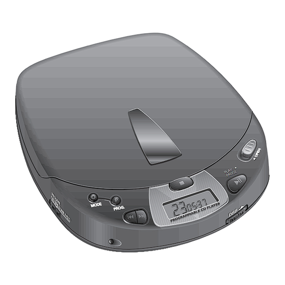
Portable compact disc player
TABLE OF CONTENTS
Technical specification ......................................................1-1
Connections and controls ..................................................1-2
Feature overview ...............................................................1-2
Accessories .......................................................................1-3
Safety warnings .................................................................1-4
Service hints ......................................................................2-1
Service tools ......................................................................2-1
Handling chip components ................................................2-2
Service test program .................................................2-3...2-4
Start-up procedure.............................................................2-5
Fault finding guide .....................................................2-5...2-9
Blockdiagram .....................................................................3-1
Pinning of ICs ....................................................................3-2
Published by Consumer Electronics
Printed in The Netherlands Copyright reserved Subject to modification
AZ7261/
AZ7262/
AZ7263/
AZ7264/
AZ7266/
AZ7267/
AZ7268/
Circuit diagrams
Supply/control part ........................................................4-1
Servo part......................................................................4-2
Signal processing part...................................................4-3
Audio part......................................................................4-4
Copperside view............................................................4-5
Componentside view .....................................................4-6
Exploded view ...................................................................5-1
Mechanical partslist ...........................................................5-1
Electrical partslist ......................................................6-1...6-3
00/01/01Z/11/14/17
00/05
11
06/11/13
17
00/05/06
00/01/05/10/11/17
SHARON PLATFORM 1
CLASS 1
LASER PRODUCT
© 4822 725 24981
CS 46 158
Advertisement
Table of Contents

Related Manuals for Philips AZ7261

Summary of Contents for Philips AZ7261
-
Page 1: Table Of Contents
Portable compact disc player AZ7261/ 00/01/01Z/11/14/17 AZ7262/ 00/05 AZ7263/ AZ7264/ 06/11/13 AZ7266/ AZ7267/ 00/05/06 AZ7268/ 00/01/05/10/11/17 SHARON PLATFORM 1 TABLE OF CONTENTS Technical specification ............1-1 Circuit diagrams Connections and controls ..........1-2 Supply/control part ............4-1 Feature overview ...............1-2 Servo part..............4-2 Accessories ...............1-3 Signal processing part...........4-3... -
Page 2: Technical Specification
TECHNICAL SPECIFICATION General Headphone out (load impedance 16Ω, except crosstalk) Dimensions (WxHxD) : 134x30.5x154mm Output power : 2x10mW ±2dB Weight without batteries : 250g Frequency response (max vol.) : 20Hz-20kHz within 8dB S/N ratio (unw.) : >80dB (83dB typ.) S/N ratio (A-wght) : >82dB (85dB typ.) Power supply modes THD+N (1kHz, 1mW) -
Page 3: Connections And Controls
2;.........Button for starting and pausing CD play / CD OUT......Headphone and remote control socket (3.5mm) 4.5 V DC ......Socket for external power supply Battery compartment..for inserting batteries FEATURES SHARON PLATFORM 1 FEATURES SHARON 1 AZ7261 AZ7262 AZ7263 AZ7264 AZ7266 AZ7267 AZ7268 RESUME FUNCTION... -
Page 4: Accessories
ACCESSORIES SHARON PLATFORM 1 CS 46 161... -
Page 5: Safety Warnings
SAFETY WARNINGS © ñ WARNING WAARSCHUWING All ICs and many other semiconductors are susceptible to Alle IC´s en vele andere halfgeleiders zijn gevoelig voor electrostatic discharges (ESD). Careless handling during electrostatische ontladingen (ESD). repair can reduce life drastically. Onzorgvuldig behandelen tijdens reparatie kan de levensduur When repairing, make sure that you are connected with the drastisch doen vermindern. -
Page 6: Service Hints
SERVICE HINTS REPAIR POSITION COMPONENTSIDE REPAIR POSITION COPPERSIDE To get access to the componentside of the To get access to the copperside of the printed circuit board proceed as follows: printed circuit board proceed as follows: 1. Disconnect DC-cable and headphone 1. -
Page 7: Handling Chip Components
HANDLING CHIP COMPONENTS CS 46 164... -
Page 8: Service Test Program
SERVICE TEST PROGRAM 5. SERVO TEST Purpose:Check door- and inner-switch, movement of slide servo and acceleration of discmotor. • To enter the servo test start service test program and 1. PRELIMINARY SETUP press the “PLAY” button. • To enter the service test program hold the keys “PLAY” •... - Page 9 FLOW CHART To enter service test program hold PRELIMINARY “PLAY” & “STOP”-button depressed, SETUP while turning POWER ON. ATTENTION: LASER IS SWITCHED ON Display shows → AVOID DIRECT EXPOSURE TO BEAM !! software-version (e.g. “85 ”) MAIN MENU Remark: Playback test can only “NEXT”...
-
Page 10: Start-Up Procedure
START-UP PROCEDURE MAIN FAULT FINDING GUIDE FAULT FINDING GUIDE FOCUS PATH Start-up procedure for ext.DC supply, CHECK POWER OFF CHECK no accu inserted, hold-switch in off pos., CD-DRIVE AND (stand-by) FOCUS PATH resume-mode off, CD-door closed. SERVO CIRCUITS enter PLAY service program turntable and pressed ? -
Page 11: Fault Finding Guide
FAULT FINDING GUIDE LIGHTPATH CHECK LIGHTPATH laser light ? supply +3.5 OK ? voltage betw. pin 2/3 of 1800 =1.2V ? repair replace CD-drive pin 64 of 7830 =high ? voltage on pin 4 of 1800 check =1.2V ? CD7 7830 check supply +1.2, 2800/3800... - Page 12 FAULT FINDING GUIDE TURNTABLE MOTOR PATH CHECK TURNTABLE MOTOR PATH discmotor turning ? connections turntable and to/from CD-drive disc free ? OK ? mechanical repair obstruction ? connections focus OK ? remove replace PWM-output CHECK obstruction CD-drive on pin 33 of FOCUS PATH 7830 ? eye-pattern...
- Page 13 FAULT FINDING GUIDE RADIAL TRACKING CHECK RADIAL TRACKING enter service program “SERVO TEST” slide movement ? servo signals on slide motor connections servo signals to/from CD-drive on pin 37 of OK ? 7950 ? enter replace repair check check service program CD-drive connections servo driver 7950...
- Page 14 FAULT FINDING GUIDE FUNCTIONAL TEST FUNCTIONAL TEST all previous tests passed start-over drive&servo checks mechanical obstruction ? remove obstruction set sensitive to temperature localize temperature sensitive part&repair replace CD-drive still errors during playback replace set SET REPAIRED CS 46 171...
-
Page 15: Blockdiagram
BLOCKDIAGRAM DISPLAY ILLUMINATION +µP P TMP47C823F RESET LCD DRIVER IR-RECEIVER RESET (not on all versions) CLOCK GEN. 12bit TIMER & TIMING COUNTER 4MHz RC5-in I/O PORTS DISC KEYBOARD TURNTABLE MOTOR CORD-RC CIRCUIT +3.5 (not on all versions) TRACK SERVO from/to SUPPLY/CHARGE CIRCUIT 8.46MHz FOCUS LASER... - Page 16 PINNING OF INTEGRATED CIRCUITS MPC1718 – 4-STAGE PWM SERVODRIVER Name Direction Description ––––––––––––––––––––––––––––––––––––––––––––––––––––––––––––––––––––––––––––––––––––––––––––––––––––––––––– → servo driver Hin2 power supply for H-bridge output section 2 SAA7372 – DECODER AND DIGITAL SERVO IC CD7 servo driver → disc motor Hout2A H-bridge PWM output 2A DC/DC converter 2 →...
-
Page 17: Supply/Control Part
Explanation of itemnumber extentions: 7280 C 6 EVQ PJX ESE11SH1 TEST 12-bit 7281A C 5 Timing Generator Interval Timer 8-bit Serial AZ7261,AZ7262,AZ7266,AZ7267,AZ7268 ..A 7282A C 8 Timer/Counter Interface 7283A C11 Clock Generator AZ7263 ............A+F+J (2ch) 7284A C 6 XOUT Watchdog AZ7264 ............ - Page 18 2960 H10 INNERSW 2961 H11 Explanation of itemnumber extentions: Supply voltages 2962 H11 +3.5 2963 H 8 Sldm+ AZ7261,AZ7262,AZ7266,AZ7267,AZ7268 ..A +A..Battery or ext. DC 3405 C14 7950 3910 G 3 +3.5 AZ7263 ............A+F+J +S..Switched +A MPC1718 3922 G 2 3923 H 2 AZ7264 ............
-
Page 19: Signal Processing Part
OUTPUT MOTO2 TIMING 3905 C 5 Explanation of itemnumber extentions: 3992 STAGES 3973 H 8 150p HFIN 3974 K7 1.8V AZ7261,AZ7262,AZ7266,AZ7267,AZ7268 ..A 2988 3819 3820 3975 C 4 VSSA3 MOTO1 3981 3985 3989 2984 3980 I 5 AZ7263 ............A+F+J... -
Page 20: Audio Part
Supply voltages This circuit diagram shows a summary of all 5368X C13 possible versions. For components used in 5369X D13 AZ7261,AZ7262,AZ7266,AZ7267,AZ7268 ..A +A..Battery or ext. DC 5370X A13 specific versions see table next right. 5371X A13 AZ7263 ............A+F+J +S.. -
Page 21: Printed Circuit Board Copperside View
5950 D 4 2255 Explanation of itemnumber extentions: 2816 D 4 3322 B 4 3806 C 3 5951 D 5 AZ7261,AZ7262,AZ7266,AZ7267,AZ7268 ..A 2817 B 4 3323 C 4 3807 C 3 5952 E 5 5952 AZ7263 ......A+F+J 2818 B 4... -
Page 22: Componentside View
3276A C 2 3277X C 2 Explanation of itemnumber extentions: +DC GND RC5 3280A C 2 AZ7261,AZ7262,AZ7266,AZ7267,AZ7268 ..A 3281A D 2 AZ7263 ......A+F+J 3282A C 2 AZ7264 ......A+D 3283A C 2 1450F... -
Page 23: Exploded View
EXPLODED VIEW MECHANICAL PARTSLIST 4822 443 10305 DOOR-CD ASSEMBLY AZ7261, AZ7263, AZ7266, AZ7267, AZ7268 (not for /17) 4822 443 10306 DOOR-CD ASSEMBLY AZ7261, AZ7263, AZ7266, AZ7267, AZ7268 (only for /17) 4822 443 10311 DOOR-CD ASSEMBLY AZ7262, AZ7264 (not for /17) -
Page 24: Electrical Partslist
ELECTRICAL PARTSLIST CAPACITORS CAPACITORS RESISTORS ––––––––––––––––––––––––––––––––––––––––––––––––––––– ––––––––––––––––––––––––––––––––––––––––––––––––––––– ––––––––––––––––––––––––––––––––––––––––––––––––––––– 2453 © 4822 122 33496 100nF 2980 © 5322 122 32452 47pF 3338 © 4822 051 20392 3,9kΩ 0,1W 2454 © 4822 122 33891 3,3nF 2981 © 4822 122 33496 100nF 3345 © 4822 051 20223 22kΩ... - Page 25 RESISTORS RESISTORS ––––––––––––––––––––––––––––––––––––––––––––––––––––– ––––––––––––––––––––––––––––––––––––––––––––––––––––– 3805 © 4822 051 20103 10kΩ 0,1W 3988 © 4822 051 20332 3,3kΩ 0,1W 3806 © 4822 051 20103 10kΩ 0,1W 3989 © 4822 051 20223 22kΩ 0,1W 3807 © 4822 051 20103 10kΩ 0,1W 3990 © 4822 051 20332 3,3kΩ...
- Page 26 INTEGRATED CIRCUITS ––––––––––––––––––––––––––––––––––––––––––––––––––––– 7280 © 4822 209 71448 NJM2903M 7300 © 4822 209 33164 TDA1545AT/N2 7320 © 4822 209 33165 TDA1308T/N1 7322 © 4822 209 33165 TDA1308T/N1 7400 © 4822 209 13566 µP TMP47C823F SHARON1-PB1 7425 © 4822 209 12991 PST9127N 7800 ©...
Need help?
Do you have a question about the AZ7261 and is the answer not in the manual?
Questions and answers