Table of Contents
Advertisement
Quick Links
SPEED LIMIT RC
Feature:
EPO Flex Foam
High Scale Mechanical Folding Wings
Excellent Performance and Stability!
Working 2-Stage(best for performance)
/ 3-Stage(full-scale plane) Flaps
Super High Scale and Details
Working High-Scale Navigation Lights
Durable Metal Retracts
BlitzRCWorks / Lanxia g reserves the right to modify the specification or
printing errors without prior notice.
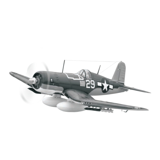
F4U
F 4 U
SPEED LIMIT RC
Warning:
A R/C model airplane is not a toy and is not intended for use by children without
direct adult supervision. It is not suitable for children under 14 years. It is
essential to read and follow all the instructions and warnings carefully in the
manual prior to assembly, setup or use, in order to operate correctly, avoid
damage to the product, personal property and cause serious injury. If you are a
beginner, it is recommended to seek experienced assistant.
As the user of this product, you are solely responsible for operating in a manner
that does not endanger yourself and others or result in damage to the product or
the property of others.
www.speedlimitrc.com
Advertisement
Table of Contents

Summary of Contents for Speed Limit F4U Corsair
- Page 1 SPEED LIMIT RC F 4 U Feature: EPO Flex Foam High Scale Mechanical Folding Wings Excellent Performance and Stability! Working 2-Stage(best for performance) / 3-Stage(full-scale plane) Flaps Super High Scale and Details Working High-Scale Navigation Lights Durable Metal Retracts SPEED LIMIT RC...
-
Page 2: Meaning Of The Icons
F-4U SPEED LIMIT RC Instruction Manual Meaning of the icons. 7.Do not attempt to catch the model while flying. WARNING!: this symbol indicates where caution is essential to avoid injury to yourself or others . 8.Not recommended for children under 14years old,... - Page 3 F-4U SPEED LIMIT RC Instruction Manual Retract control switch Flap control switch Vector SW switch Dual rates servo SW switch Throttle, rudder rocker Elevator aileron rocker Mode 1/2 SW switch Mixed control switch SW-A (Function switching over 1, 2 mode) SW-B (CH7,CH8,CH9 channel switching over);...
- Page 4 F-4U SPEED LIMIT RC Instruction Manual Specification: KIT(Airframe Only) Package Includes: Length: 981mm 38.6" 1x Retract System Set Wingspan: 1200mm (47.2") 2x Folding Wing Mechanism Propeller Diameter:12×6 Flying Weight:2360g Thrust:≥2600g RTF (Ready To Fly) Package Includes: 1x12 Channel Radio System...
- Page 5 F-4U SPEED LIMIT RC Instruction Manual Rear Landing Steering Installation.(12-13) Rear retract installation.(3-4) Rudder tiger tail installation.(14-16) Linkage Tubes Installation.(5-9) Φ3×150mm Φ3×300mm Rudder Servo Installation. (10-11) Rudder Bracket Installation.(17-18) www.speedlimitrc.com...
- Page 6 F-4U SPEED LIMIT RC Instruction Manual Elevator Bracket Installation.(19-20) 2×6mm Tail LED Light Installation. (29-30) Rudder Servo Installation.(21-25) 650mm Using Metal Gear Servo With 300mm Length Wire. Decorating parts installation.(31-32) 2×6mm Elevator Servo Installation. (26-28) Gluing The Fuselage Together.(33-34) Use Metal Gear Servo with 200mm Length Wire.
-
Page 7: Elevator Installation
F-4U SPEED LIMIT RC Instruction Manual Rear Retract Door Installation.(49-52) Making the Cover.(35-40) The cover is for ahjusting the tail wheel and replacing the tail landing gear. Elevator push rods installation.(41-43) Elevator Installation.(53-57) 352mm Cowling Installation. (44-46) 1.7×18mm 1.7×15mm Mount The Horizontal Tail to the Fuselage. -
Page 8: Motor Installation
F-4U SPEED LIMIT RC Instruction Manual ESC Installation. (65-68) Elevator Control Surface Clevis Rudder Installation.(58-61) Installation.(57) 2.5×14mm 1.7×18mm 1.7×22mm Cowling installation.(69) Cockpit installation.(70-81) Rudder Control Surface Clevis Motor Installation.(62-68) Magnet installation. (70-71) Installation.(61) Installing the Motor Mount.(62-64) 2×6mm Canopy Magnet Installation. -
Page 9: Main Wing Installation
F-4U SPEED LIMIT RC Instruction Manual Rear canopy installation.(74) Main Wing Installation (82-104) LED installation.(82-83) 1000mm Front canopy installation. (75-76) Folding Wing Drive Installation. (84-85) Using Screw Servo With 650mm Length Wire. Pilot installation. (77-81) .(86-87) Aileron Horns and Clevis Installation Aileron Servo Installation.(88-90) - Page 10 F-4U SPEED LIMIT RC Instruction Manual Machine Guns Installation. (97-100) 2×6mm Push rods installation. (91-92) 40mm 25mm Machine Guns Panel Installation.(93-94) Wire Loom Tube Wiring Instllation.(101-104) 350mm LED Light Installation. (95-96) Using LED Light with 650mm Wire Length. www.speedlimitrc.com...
- Page 11 F-4U SPEED LIMIT RC Instruction Manual Mid-Wing Section Flaps Instllation. (106-107) Installation.(105-126) Retract doors Installation. 2×6mm Installing the retract door push rods. Installing the door push rods.(116-121) Flap servos Installation.(108-109) 1.7×22mm 1.7×24mm The signal wire length is 150mm 2×6mm (Left is reverse servo).
- Page 12 F-4U SPEED LIMIT RC Instruction Manual Main retract installation (122-123) Main wing wirings.(130-131) 20.6mm Front landing gear door installation Indentifying the wires. (132) (124-126) 2.5×14mm 2×6mm Oil cooler installation.(133-134) Main Wing Installation.(127-134) Fastening the complete main wing together with the fuselage.(135-136) M3×12mm...
-
Page 13: Connect The Battery
F-4U SPEED LIMIT RC Instruction Manual Flaps channel wiring (145) BEC 5V output wiring (146) PCB Controller Installation.(137-139) Folding wing controller installation Led controller installation (138) (137) LED Channel Wiring (147) Folding Wing Channel Wiring (148) Radio receiver wiring setup. -
Page 14: Throttle Calibration
F-4U SPEED LIMIT RC Instruction Manual Rudder Right.(160) (161) Aileron Left. Insert 8x AA Batteries to the Radio Transmitter. (154-155) Throttle calibration. (156) Aileron Right. (162) Flap Switch.(163) 1,Turn on the transmitter 2,Connect the battery to “Beep-beep”will sound and set the throttle stick... -
Page 15: Propeller Installation
F-4U SPEED LIMIT RC Instruction Manual Propeller installation .(168-169) Decorating Parts Warning: First, ensure the motor is operating normally before installing the propeller. Next, make sure the propeller hub and blades are tighten and mounted correctly Installation.(177-185) to the motor shaft to prevent any accident. - Page 16 F-4U SPEED LIMIT RC Instruction Manual Applying the Water Decals.(186-195) CG debugging.(196) 78mm www.speedlimitrc.com...
-
Page 17: Parts List
F-4U SPEED LIMIT RC Instruction Manual Parts List . × √ √ F4U-B029 Servo 650mm Screw servo for √ √ √ F4U-B030 Quantity Name folding wing √ √ √ LED light F4U-B031 √ √ √ F4U-B001 Left fuselage √ √... -
Page 18: Problem Solving
F-4U SPEED LIMIT RC Instruction Manual B013 B014 B015 B016 F4U Pre-flight check B017 B018 B019 B020 B021 B022 B023 B024 B025 B026 B027 B028 Problem solving B029 B030 B031 B032 B033 B034 B035 B036 rotary. B037 B038 B039 B040...
Need help?
Do you have a question about the F4U Corsair and is the answer not in the manual?
Questions and answers