Table of Contents
Advertisement
Quick Links
Instructions - Parts
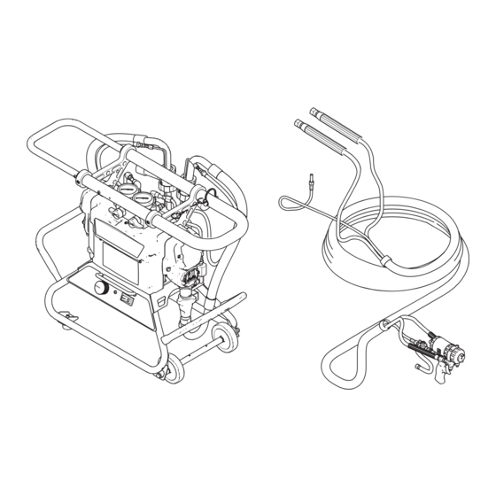
Portable Plural Component Sprayer
For spraying 1:1 mix ratio formulated no-heat polyurethane foams and dispensing 1:1 mix
ratio polyurea joint-fill materials. For professional use only. Not approved for use in
European explosive atmosphere locations.
2000 psi (14 MPa, 138 bar) Maximum Working Pressure
See page 3 for a list of models.
Important Safety Instructions
Read all warnings and instructions in all
supplied manuals. Save all instructions.
E-8p
3A1602H
EN
TI17120a
Advertisement
Table of Contents
Troubleshooting

Summary of Contents for Graco Reactor E-8p 3A1602H
- Page 1 Instructions - Parts E-8p 3A1602H Portable Plural Component Sprayer For spraying 1:1 mix ratio formulated no-heat polyurethane foams and dispensing 1:1 mix ratio polyurea joint-fill materials. For professional use only. Not approved for use in European explosive atmosphere locations. 2000 psi (14 MPa, 138 bar) Maximum Working Pressure See page 3 for a list of models.
-
Page 2: Table Of Contents
Lock/Unlock Handle ..... 14 Graco Standard Warranty ....58 Install 38 mm Spout Adapter . -
Page 3: Systems
See page 13 for detailed electrical requirements. ★ Approvals: 9902471 Conforms to ANSI/UL Std. 73 Certified to CAN/CSA Std. C22.2 No. 68 Related Manuals Manuals are available at www.graco.com. Manual Description 313213 ® Probler P2 Spray Gun Instruc- Manual Description... -
Page 4: Warnings
Warnings Warnings The following warnings are for the setup, use, grounding, maintenance, and repair of this equipment. The exclama- tion point symbol alerts you to a general warning and the hazard symbols refer to procedure-specific risks. When these symbols appear in the body of this manual, refer back to these Warnings. Product-specific hazard symbols and warnings not covered in this section may appear throughout the body of this manual where applicable. - Page 5 Warnings WARNING SKIN INJECTION HAZARD High-pressure fluid from gun, hose leaks, or ruptured components will pierce skin. This may look like just a cut, but it is a serious injury that can result in amputation. Get immediate surgical treatment. • Do not spray without tip guard and trigger guard installed. •...
- Page 6 Warnings WARNING EQUIPMENT MISUSE HAZARD Misuse can cause death or serious injury. • Do not operate the unit when fatigued or under the influence of drugs or alcohol. • Do not exceed the maximum working pressure or temperature rating of the lowest rated system component.
-
Page 7: Important Isocyanate (Iso) Information
Important Isocyanate (ISO) Information Important Isocyanate (ISO) Information Isocyanates (ISO) are catalysts used in two component materials. Isocyanate Conditions Spraying or dispensing fluids that contain isocyanates creates potentially harmful mists, vapors, and atom- ized particulates. • Read and understand the fluid manufacturer’s warnings and Safety Data Sheet (SDS) to know specific hazards and precautions related to isocyanates. -
Page 8: Material Self-Ignition
Important Isocyanate (ISO) Information Keep Components A and B For all applications except spray foam Separate Spraying or dispensing fluids that contain isocyanates creates potentially harmful mists, vapors, and atomized Cross-contamination can result in cured material in fluid particulates. lines which could cause serious injury or damage equipment. -
Page 9: Foam Resins With 245 Fa Blowing Agents
Important Isocyanate (ISO) Information Foam Resins with 245 fa Blowing Agents Some foam blowing agents will froth at temperatures above 90°F (33°C) when not under pressure, especially if agitated. To reduce frothing, minimize preheating in a circulation system. Changing Materials NOTICE Changing the material types used in your equipment requires special attention to avoid equipment damage... -
Page 10: Overview
Overview Overview The Reactor E-8p is a portable, electric-powered, 1:1 mix ratio proportioner. It is for use with formulated no-heat polyurethane foams that may be applied with impingement mix spray guns and for use with polyurea joint fill materials that may be applied with static mix guns. -
Page 11: Component Identification
Component Identification Component Identification BACK VIEW FRONT VIEW TI17121a . 1: Component Identification Key: Pump A Pump B Fluid Pressure Gauges Recirc/Spray and Overpressure Relief Valves Control Panel Electric Motor and Drive Housings Hose Bundle Spray Gun Recirculation Tubes Air Line Inlet (quick-disconnect fitting) Outlet Hose Connections Power Cord Lift Ring/Handle/Hose Rack... -
Page 12: Controls And Indicators
Controls and Indicators Controls and Indicators Status Indicator Motor/Pump Control Function Knob Power Status Switch Codes TI17123b . 2: Controls and Indicators Power Switch STATUS Indicator Powers the Reactor E-8p on and off. Indicates system status, including power and error codes. -
Page 13: Setup
Setup Setup Location Grounding • The Reactor E-8p should always be used on a level surface. • Do not expose the Reactor E-8p to rain. The equipment must be grounded. Grounding reduces the risk of static and electric shock by Electrical Requirements providing an escape wire for the electrical current due to static build up or in the event of a short circuit. -
Page 14: Lock/Unlock Handle
Setup Lock/Unlock Handle Install 38 mm Spout Adapter Lock the handle when the sprayer is moved, laid on its The sprayer is supplied with a 40 mm spout adapter. side, or turned upside down. Install 38 mm spout adapters if necessary. Unlock 1. -
Page 15: Install Optional Recirculation Kit
(501). Set A and B side parts aside. NOTE: Ensure that there is enough space to dispense Elbow fittings (511) are not used with recirculation Graco ISO pump oil in the wet cup through the pump setup. cover. - Page 16 Setup 12. Install fluid tubes (36). 3A1602H...
-
Page 17: Connect Fluid Hoses
Setup Connect Fluid Hoses Connect Main Air Supply NOTE: The Reactor E-8p requires 4 scfm Connect fluid supply hoses to outlet hose connections . 9 and F . 10). Red hoses for component A (ISO), (0.112 m /min) compressed air for the air operated blue for component B (RES). - Page 18 Setup A Recirculation A (ISO) B Recirculation A (ISO) B (RES) Compressed Air Line B (RES) Recirculation Gun Manifold Kit 249523 (only compatible with Fusion Air Purge Gun) TI7134A . 10: Hose and Air Connections - Recirculation Hose Kit 24M654 3A1602H...
-
Page 19: Fill Wet-Cups
Keep the felt washers in the pump wet-cups saturated The standard system circulates material from the fluid with Graco ISO pump oil, Part No. 217374. The lubricant manifold back to the supply container. To circulate creates a barrier between the ISO and the atmosphere. -
Page 20: Purge Air And Flush Fluid
Setup Purge Air and Flush Fluid 6. Set function knob to Slow Recirc or Fast Recirc 1. Insert inlet tubes into pails of solvent. TI17128b . 15 7. When material exits both recirculation tubes, set the function knob to Stop/Park TI17126a . -
Page 21: Connect Fluid Inlet Tubes
Setup Connect Fluid Inlet Tubes 7. Set function knob to Slow Recirc or Fast Recirc 1. Loosen containment knob. 2. Remove suction tube caps and place in contain- ment tray. TI17128b . 21 3. Insert each fluid inlet tube through the pour spout on the appropriate five-gallon pail. -
Page 22: Spraying
Spraying Spraying 6. Check fluid pressure gauges to ensure proper pres- sure balance. If imbalanced, reduce pressure of higher component by slightly turning Recirc/Spray valve for that component toward Recirc, until NOTE: For air operated guns, air is supplied to spray gauges show balanced pressures. -
Page 23: Pressure Relief Procedure
Pressure Relief Procedure Pressure Relief Shutdown Procedure NOTE: For longer breaks (more than 10 minutes), use the following procedure. If you will be shut down for more than three days, perform the Flushing procedure, page 25, first. NOTE: If using the Manual 2K gun, refer to the Manual Trapped air can cause the pump to cycle 2K gun instruction manual. -
Page 24: Maintenance
Maintenance Maintenance 5. Use solvent to wipe down fluid inlet tubes. 6. Install suction tube caps on each fluid inlet tube and Check pump wet-cups fluid level daily. Refer to Fill • rest in the containment tray. Tighten the contain- Wet-cups, page 19. -
Page 25: Flushing
Flushing Flushing 3. Remove both recirculation tubes from material pails and secure each one to a dedicated waste con- tainer. Flush equipment only in a well-ventilated area. Do not spray flammable fluids. • Generally, flush if you will be shut down for more than 3 days. - Page 26 Flushing 9. Purge gun hoses. a. Disconnect hoses from gun and secure to a pail of solvent. b. Turn Recirc/Spray valve A to Spray. TI17136a . 45 c. Open gun into waste container A. d. Set function knob to Slow Recirc until hose is flushed.
-
Page 27: Troubleshooting
Troubleshooting Troubleshooting Status Codes 2. Reduce pressure of higher component by slightly turning Recirc/Spray valve for that component toward Recirc, until gauges show balanced pres- Determine the status code by counting the number of sures. times the status indicator blinks. In this example, B side STATUS Indicator pressure is higher, so... - Page 28 Troubleshooting Status Code 1 and 2 Settings (Default) 1. Locate switch SW2 on the control board. 2. Set the four DIP switches to the desired positions. TI7023a TI7024a See F . 48 and Table 2. . 48. DIP Switch (SW2) Settings Table 2 : Status Code 1 and 2 Settings DIP Switch and Function...
- Page 29 Troubleshooting Status Code 6: High Motor Temperature Motor is running too hot. 1. Motor temperature too high. Reduce pressure duty cycle, gun tip size, or move Reactor E-8p to a cooler location. Allow 1 hour for cooling. 2. Check fan operation. Clean fan and motor housing. Status Code 7: No Cycle Counter Switch Input Have not received input from cycle counter switch for 10...
-
Page 30: Troubleshooting Chart
Troubleshooting Troubleshooting Chart Problem Cause Solution Reactor E-8p does not operate. No power. Plug in power cord. Cycle Motor Power off then on to reset breaker. Motor does not operate. Power turned on with function knob Set function knob to Stop/Park set to a run position. - Page 31 Troubleshooting Problem Cause Solution Pressure is higher on one side Pump intake valve partially plugged. Clean pump intake valve. See page when setting pressure with function knob. Air in hose. Fluid is compressible. Purge air from hose. Unequal size hoses or unequal Use matching hoses, or balance hose construction.
- Page 32 Troubleshooting Problem Cause Solution A side rich; lack of B side. A side gauge is low. B side restriction downstream of gauge. Check gun check valve screen, mix module, or mix manifold restrictor. B side gauge is low. B side material supply problem. Check B side inlet strainer and pump intake valve.
-
Page 33: Repair
Repair Repair Before Beginning Repair Recirculation/Spray Valves 1. See Before Beginning Repair, page 33. Relieve pressure, page 23. Repairing this equipment requires access to parts which may cause electric shock or other serious injury if work is not performed properly. Have a 2. -
Page 34: Displacement Pump
Repair Displacement Pump To remove entire pump assembly 1. Loosen nut and press the inlet tube down away from the pump intake valve. Displacement pump repair and parts infor- mation is included in manual 311076, which 2. Disconnect swivel (32) from pump outlet and loosen is supplied with your unit. -
Page 35: Replace Function Knob/Potentiometer
Repair Replace Function 10. Reconnect potentiometer wires to J2 as shown in Fig 12. Knob/Potentiometer 1. See Before Beginning Repair, page 33. Relieve pressure, page 23. 2. Insert pin through cart handle and lock with lanyard. ti17464a . 55 3. Carefully lay sprayer on its side on a level surface. 4. - Page 36 Repair ti17465a . 56. Function Knob/Potentiometer 3A1602H...
-
Page 37: Control Board
Repair Control Board Table 3: Control Board Connectors (see F . 58) Board Power Bootup Check Jack Description NOTE: There is one red LED (D11) on the board. Power Main power from breaker must be on to check. See F . - Page 38 Repair LINE Black Twin Flat Cable Motor Function J11 (120 V Knob Black Board) CONTROL Yellow BOARD Cycle Yellow Counter 249434 (120 V) Black Status SW2 (see page 28 Indicator to adjust settings) Black Black White Black Sheath Black Sheath Jumper White not used...
-
Page 39: Pressure Transducers
Repair Pressure Transducers Drive Housing Removal 1. See Before Beginning Repair, page 33. Relieve pressure, page 23. 1. See Before Beginning Repair, page 33. Relieve 2. Insert pin through cart handle and lock with lanyard. pressure, page 23. 3. Carefully lay sprayer on it’s side on a level surface. 1. - Page 40 Repair ti17467a . 59: Pressure Transducer Connection 3A1602H...
- Page 41 Repair NOTE: B side crankshaft (210) includes the cycle 6. Disconnect cart handles. counter magnet (224). When reassembling, be sure to a. Remove screws (42) from handle (37). install crankshaft with magnet on B side. If replacing crankshaft, remove magnet (224). Reinstall b.
-
Page 42: Cycle Counter Switch Replacement
Repair Cycle Counter Switch Replacement NOTE: B side drive housing cover (227) includes the cycle counter switch (223), mounted in the cover. When reassem- bling, be sure to install cover with switch on B side. Feed the cable under the electric motor and through the grommet and connect to the control board. -
Page 43: Electric Motor
Repair Electric Motor 10 (x4) Test Motor If motor is not locked up by pumps, it can be tested using a 9 V battery. 1. Open recirculating valves, disconnect J4 or J11 from control board, see F . 58, page 38. 13 (x7) 2. -
Page 44: Motor Brushes
Repair Motor Brushes Installation See F . 62, page 43. NOTE: Replace brushes worn to less than 1/2 in. (13 mm). Brushes wear differently on each side of motor; 1. If replacing motor, install fan assembly and fan check both sides. Brush Repair Kit 287735 is available; mount threaded bushing on new motor. -
Page 45: Spout Adapter
Repair Spout Adapter 3. Connect 38 mm or 40 mm spout adapter. a. Place spout adapter (404) on a flat level sur- The sprayer is supplied with a 40 mm spout adapter. Follow these instructions to install 38 mm spout adapt- face. -
Page 46: Parts
Parts Parts 120 V and 240 V Fusion Air Purge System Packages 120 V and 240 V Fusion CS System Packages 120 V and 240 V P2 System Packages 120 V and 230 V Manual 2K System Packages ti17122a System with Air Operated Gun shown Bare Proportioner Hose System... - Page 47 Parts 259082 (120V) and 259083 (240V), Bare Proportioner 36 (2x) 34 (2x) 33 (2x) 31 (2x) 32 (2x) 29 (4x) 48 (2x) 30 (2x) 49 (2x) 47 (2x) 53 (2x) 35 (2x) 51 (2x) 52 (4x) Apply sealant to threads. Cover entire surface of sensor probe with TI17471b lubricant before assembling onto motor...
- Page 48 Parts 259082 (120V) and 259083 (240V), Bare Proportioner (continued) 92▲ 10 (4x) 13 (7x) 10 (4x) 11 (4x) TI17472a 3A1602H...
- Page 49 Parts 259082 (120V) and 259083 (240V), Bare Proportioner (continued) 37 (2x) 40 (2x) 88 (2x) 41 (4x) 10 (2x) 43 (2x) 42 (2x) 5 (2x) 84 (2x) 29 (2x) 54 (2x) 55 (2x) 91 (2x) 7 (4x) 56 (2x) 3 (2x) 3A1602H...
- Page 50 Parts 259082 (120V) and 259083 (240V), Bare Proportioner (continued) Ref. Part Description Qty. Ref. Part Description Qty. 249630 HOSE, component B (resin), 1/4 in. 24J139 CART (6 mm) ID; thermoplastic hose; 1/4 16H888 GROMMET, 7/8 in. ID 16F820 WHEEL, caster npsm(f) x 48 in.
- Page 51 Parts 24L885, 120 V Bare Proportioner 24L979, 240 V Bare Proportioner ‡221 208* 209* 210* 215‡ 211* 220‡ 207‡ †212 †213 †214 †213 222‡ ◆216 220‡ 217◆ 207‡ TI17473a Ref. Part Description Ref. Part Description 217◆ 196762 PIN, straight 24E355 MOTOR, electric; 120 V 195150 NUT, jam, pump 24E356 MOTOR, electric;...
- Page 52 Parts 3/8 in. ID x 50 ft Insulated Hose Bundle without Recirculation Lines with Air Hose, 24M653 Ref. Part Description 16V331 HOSE, fluid (component A), mois- ture guard; grounded, 3/8 in. 302 (Ref) (9.5 mm) ID; no. 5 JIC fittings (mxf); 50 ft (15 m) 24M671 HOSE, fluid (component B);...
- Page 53 Parts Recirculation Manifold, 24J147 Ref. Part Description 24K993 MANIFOLD, recirculation 111763 ELBOW; 1/4 npt (mbe) 239914 VALVE, recirc/spray; includes items 503a, 503b 503a 15E022 . SEAT 503b 111699 . GASKET 224807 BASE, valve 187625 HANDLE, valve, drain 111600 PIN, grooved 503a 113641 GAUGE, pressure, fluid 503b...
- Page 54 Parts Pour Spout Adapter Ref. Part Description Part Description 16H539 PLATE, crush, inlet 24J155 40 mm A Side Pour Spout Adapter 16H540 CAP, spout, pour 24J766 40 mm B Side Pour Spout Adapter HOUSING, inlet tube, 403a or 24M052 38 mm B Side Pour Spout Adapter 403b 24M053 38 mm A Side Pour Spout Adapter...
-
Page 55: Suggested Spare Replacement Parts
Suggested Spare Replacement Parts Suggested Spare Manual 2K Gun Replacement Parts Manually opened and closed, two-component gun. See manual 332198. Pail Heater, 16U623 Part Description 24K984 DRYER, desiccant Flexible band heaters for 5 gallon pails. 246385 STRAINER, pump inlet 24K983 SWITCH, motor power, with circuit breaker Recirculation Hose Kit, 24M654 113641 GAUGE, pressure, fluid;... -
Page 56: Dimensions
Dimensions Dimensions 34.58 in. (87.8 cm) 24.12 in. (61.3 cm) 15.06 in. (38.3 cm) TI17120a 3A1602H... -
Page 57: Technical Data
Technical Data Technical Data Reactor E-8p Metric Maximum fluid working pressure 2000 psi 14 MPa, 138 bar Model 259082: 120 Vac, 1 phase, 50/60 Hz, 1800 W; Electrical requirements requires a single dedicated 15 A circuit Generator Size 2500 W minimum Maximum Ambient Temperature 110°F 43°C... -
Page 58: Graco Standard Warranty
With the exception of any special, extended, or limited warranty published by Graco, Graco will, for a period of twelve months from the date of sale, repair or replace any part of the equipment determined by Graco to be defective.
Need help?
Do you have a question about the Reactor E-8p 3A1602H and is the answer not in the manual?
Questions and answers